+ Reply to Thread
Page 3 of 5 FirstFirst 1 2 3 4 5 LastLast
Results 21 to 30 of 48

Thread: Current draw of typical FSAE electrical components

  1. #21
    Originally posted by Kevin Hayward:
    Rex,

    It is a bit annoying to see it on just about every post. I believe it is better not to post your affiliations or experience. Others should feel free to determine the validity of your comments based on content, not because the words come from an expert.

    Kev
    Hi Kevin,

    I have a personal dislike of 'signatures', hence I usually don't bother with one on any forums I participate in (not just FSAE). As you, I find that the content of a comment or post is usually enough to determine validity.

    Regards, Ian

  2. #22
    Senior Member
    Join Date
    Oct 2007
    Location
    Bolton, CT
    Posts
    144
    Originally posted by Pete Marsh:
    Ian,
    I addition to FSAE I think there is a market with club level motor sport for a really simple PDM. Mechanical relays and push to reset thermal overloads (the old aircraft style) are the favoured set up for many, and maybe you can simulate that behaviour, and convince them your box of tricks is smaller lighter and better.
    And good, but cheap electrical connections. The mating plugs can't cost as much or more than the unit! Many people at this level would never consider a bespoke loom with Mil Spec connectors throughout.
    I think you should also consider a "factory programmed" unit that is simply plug and play. There are plenty of people that would prefer that.

    Do that for $200.00 and I'll buy one.

    Pete
    I agree with Pete. I would definately [personally] buy one for under $200.

    There is definately a need in the non-professional motorsports and homebuilt/kit car market for a low cost, simplified, PDM. I'm sure many people would be interested in CAN capability as it is becomming even more commonplace on low budget ECUs (even the new MegaSquirt3 has built in CAN controller), but selling a unit with discrete switching capability like normal mechanical relays would further open the market.

    I would also second the thought that while Mil Spec circular connectors are nice, the need for expensive mating connectors/pins/crimper will kill your market. I would almost use scew terminals on the board and with good strain relief on the case wall.

    Cool project!
    Jim
    "Old guy #1" at UCONN Racing

  3. #23
    Originally posted by Pete Marsh:
    Ian,
    I addition to FSAE I think there is a market with club level motor sport for a really simple PDM. Mechanical relays and push to reset thermal overloads (the old aircraft style) are the favoured set up for many, and maybe you can simulate that behaviour, and convince them your box of tricks is smaller lighter and better.
    And good, but cheap electrical connections. The mating plugs can't cost as much or more than the unit! Many people at this level would never consider a bespoke loom with Mil Spec connectors throughout.
    I think you should also consider a "factory programmed" unit that is simply plug and play. There are plenty of people that would prefer that.

    Do that for $200.00 and I'll buy one.

    Pete
    Thank you too to Jim & Kevin for their comments on a 'fit and forget' style PDM.

    I think a single product that comes 'factory' configured to simulate a set of traditional relays and fuses, but can be re-configured by advanced users, could work. The purchased config can easily be factory programmed to a default accessory load set, or simply be left at the largest 'virtual' fuse rating that still protects the internal drivers and the connector.

    The only internal cost difference between a CAN and non-CAN device is a single transceiver chip, so CAN support is a no brainer. The user can opt not to buy a USB->CAN adapter initially (this would be pretty cheap too, maybe $50) and can buy one later to upgrade if they want to integrate the PDM further.

    How many outputs would make sense? Would they all need to be >>10A or would a mix of outputs be OK?

    An appropriate power connector is a Deutsch DTF13-12PA (this has 12 contacts). The mating half is $5 plus wire and they are light, sealed, robust, serviceable without tools and reasonably compact. The PDM itself could be made small enough to follow the profile of the connector and be about 60mm long (I estimate).

    A single 12pin connector offers 6 outputs turned on by 6 pull-to-ground inputs. These inputs would be compatible with the typical relay driver included in most ECUs like the Megasquirt or the PE. Power should probably be an M8 'stud' like the MoTeC PDMs and a smaller 3-pin DTF13-3P would make a good CAN + signal Gnd connector.

    I think a bespoke case would be needed, especially given the M8 stud connection. That might end up being the highest cost item, but essential for reliable operation & good heatsinking in my opinion. I still think $200 is achievable.

    Regards, Ian

  4. #24
    Ian,

    I'll throw some numbers at you. Depending on the size of the fan, you are probably looking at anywhere from 3 to 12A for the sizes that would be used in FSAE.

    The Davies Craig water pumps which are often used in FSAE can draw up to 5 or 6A.

    Fuel Pumps are where the current consumption can vary quite a bit, but normally lie in the range of 6-10A, depending on Fuel Pressure.

    Starter Motors are where it starts to get interesting, with peak turn on currents up to 200A and cranking currents between 70A and 100A.

    I think its a great idea for an off the shelf, low cost PDM. If the outputs can be PWM controlled you will definitely beat the Motec PDM on one feature.
    Stefan Nasello
    Queens University Racing - Project Manager 2009
    Rennstall Esslingen - Suspension Team 2010

    www.qfsae.com
    www.rennstall-esslingen.de

  5. #25
    Originally posted by SNasello:
    Ian,

    I'll throw some numbers at you. Depending on the size of the fan, you are probably looking at anywhere from 3 to 12A for the sizes that would be used in FSAE.

    The Davies Craig water pumps which are often used in FSAE can draw up to 5 or 6A.

    Fuel Pumps are where the current consumption can vary quite a bit, but normally lie in the range of 6-10A, depending on Fuel Pressure.

    Starter Motors are where it starts to get interesting, with peak turn on currents up to 200A and cranking currents between 70A and 100A.

    I think its a great idea for an off the shelf, low cost PDM. If the outputs can be PWM controlled you will definitely beat the Motec PDM on one feature.
    Thanks for the numbers, Stefan. I can definitely say that I do not plan to design a unit capable of controlling a starter motor, though...

    PWM control is an interesting topic. To do that requires a half-bridge electrical architecture not a simple high-side drive. You then have to deal with ground recirculation currents, so need a high current ground pin for the load as well as a high current supply pin. I'll have a think about that.

    As a general query, how would you as users expect the CAN control to work? I have some experience with the GEMS PM1 which has a very simple CAN interface. It simply takes 'virtual fuse' currents and on / off signals sent by a smart central controller on a dedicated CAN id. It does not include arbitrary CAN decoding of sensor values or have any internal control strategy. Would this be OK for you guys, or were you thinking the central controller functions would be included as well?

    Thanks, Ian

  6. #26
    Ian since it seems like you're going to get down and dirty with this..or at least contemplating it (like i do at times :P ) I'll feed you some thoughts.

    personally...i absolutely HATE screw terminals. Just as a heads up I do however realize that there's a few spots where they can be useful.

    -allow for serial communications to the micro via command terminal like terra term or something similar. This will allow for diagnostics, modification commands and so forth.

    -wouldn't be that hard to allow a CAN communicated and an analog input to drive the outputs in the same package. Have a jumper that's 2-way configurable. Position 1 allows inputs from the a-d pins on the micro (which are tied to inputs) and position 2 allows for a CAN-read in that controls the outputs, or other serial communication for that matter...CAN...rs232...etc...ours currently follows the analog input option but i would like to have CAN capability

    -current sensing. This is going to be relatively easy...why? Because you should already be using power fet's to drive these...instead of relays. The added bonus to this...is that there's fet's with a built in current sense!! Feed that guy back into the micro and it can serve as a fuse/overprotect.
    <pre class="ip-ubbcode-code-pre">
    for(I>10){
    if(T_on > 5sec){
    turn off}
    }
    </pre>

    something similar to that..where I is the sensed current and T_on is how long its been there.

    -PWM. Could do this a couple different ways. Obviously using the FET's you've already got a very viable PWM option when coupled with the micro. Either you can program it via the micro (hard set value) or do something like a small rotary pot to adjust values. The former of course allows for much more flexibility. Any output would be able to be configured as a PWM output as all the driving factor would be is the PWM output routine.

    another thing to consider is the use of a budget FPGA like a cyloneII instead of just a micro. If you do use just a micro, be careful at how fast you're clocking it...PWM takes a LOT of clock cycles...not physically...but when you look at the wasted cycles...plus the interrupting....its quite the hog on the system.

    -flyback. Most fet's have an internal diode for their protection but using that diode as a flyback diode is bad practice. Make sure that you've got flyback protection diodes in the circuit so that your transient spikes dont make something else in your circuit to go poof.

    -grounding planes. I'm assuming that you're doing this on a PCB so when you do the board...make sure you've got proper EMI isolation. If your ground planes aren't happy....it can lead to some undesired results with signals like PWM. In our application its probably not that big of a deal...but again, generally good practice.

    personally i see this box as an "everything but the starter" box. The draws of 100-150A (PLUS imagine the transients!) of the starter aren't something you're going to want to run through a PCB. even 4oz copper would require ridiculous traces and layers.

    Use the 12-pint deutsch connectors and build an SLA box that this will fit into. design retention holes to screw into the bottoms of the connector and then seal the opening with silicone or some potting....just the opening...please don't fill the whole thing...its not fun....don't ask me how i know

    This is a seriously good project and these are all things I've been working at for the last year or so. I'm still going to come back to my original comment and say that all of these ratings you're going to be able to easily find. Almost all electronics manufactures will have steady-state current loads...etc...Look around at a bunch of options and it should give you a good idea
    South Dakota State University Alum
    Electrical/Daq/Engine/Drivetrain/Tire guy '09-'14

    Go big, Go blue, Go JACKS!

  7. #27
    Originally posted by murpia:
    PWM control is an interesting topic. To do that requires a half-bridge electrical architecture not a simple high-side drive. You then have to deal with ground recirculation currents, so need a high current ground pin for the load as well as a high current supply pin. I'll have a think about that.
    before you get too far ahead of yourself with this one, the only time I'm aware that this would be necessary is if you're trying to drive a DC motor either direction...on command...and change that direction whenever you want.

    simple PWM control can be achieved with a high-side or low-side switch for fan speed and fuel pump regulation.
    South Dakota State University Alum
    Electrical/Daq/Engine/Drivetrain/Tire guy '09-'14

    Go big, Go blue, Go JACKS!

  8. #28
    Our team makes our own 'power distribution module', which is actually just a bunch of wires, relays, and fuses contained in one central location. It is very, very simple and it is easy to diagnose something like a blown fuse. It does not include the starter control (straight from the battery), it is not programmable in any way, and we like it. As a relatively low-tech team with somewhere between 0 and 1 EEs on the team at any given time, I can't honestly say anything with higher functionality would really be used.

    The point is, if you're trying to cater to a mass market of mostly mechies, the simpler the better. As an electrically illiterate person with a good rudimentary understanding of basic electron-wrangling principles (read: more than average but less than adequate), I can confirm that I did not understand roughly 70% of Johns post above. I can also confirm that any item I purchase with adjustability I will assume should be adjusted to try and make it "better". Anything that can be tinkered with, will be tinkered with. This causes problems on both the supplier side and the consumer side, since the consumer will immediately blame the product when thier tinkering inevitably causes problems or poor performance.

    All I'm saying is that you can't really be successful in making a product for both e-tards like myself and still have the higher level functionality desired by the more e-savvy people like jlangholz. This is merely my opinion, but like all designs you will probably have to make significant compromises. Personally, I'm in favour of the "set and forget" package, like Jim and Pete.

    Oh, and our fan consistently blows 15A fuses. Pretty much everything else (fuel pump, ign, ECU) is run off of 5A or 10A.
    Owen Thomas
    University of Calgary FSAE, Schulich Racing

  9. #29
    Originally posted by Owen Thomas:
    Our team makes our own 'power distribution module', which is actually just a bunch of wires, relays, and fuses contained in one central location. It is very, very simple and it is easy to diagnose something like a blown fuse. It does not include the starter control (straight from the battery), it is not programmable in any way, and we like it. As a relatively low-tech team with somewhere between 0 and 1 EEs on the team at any given time, I can't honestly say anything with higher functionality would really be used.

    The point is, if you're trying to cater to a mass market of mostly mechies, the simpler the better. As an electrically illiterate person with a good rudimentary understanding of basic electron-wrangling principles (read: more than average but less than adequate), I can confirm that I did not understand roughly 70% of Johns post above. I can also confirm that any item I purchase with adjustability I will assume should be adjusted to try and make it "better". Anything that can be tinkered with, will be tinkered with. This causes problems on both the supplier side and the consumer side, since the consumer will immediately blame the product when thier tinkering inevitably causes problems or poor performance.

    All I'm saying is that you can't really be successful in making a product for both e-tards like myself and still have the higher level functionality desired by the more e-savvy people like jlangholz. This is merely my opinion, but like all designs you will probably have to make significant compromises. Personally, I'm in favour of the "set and forget" package, like Jim and Pete.

    Oh, and our fan consistently blows 15A fuses. Pretty much everything else (fuel pump, ign, ECU) is run off of 5A or 10A.
    whoops

    on a side note, 15A for a fan...you guys must be running a 14" odd fan or something...

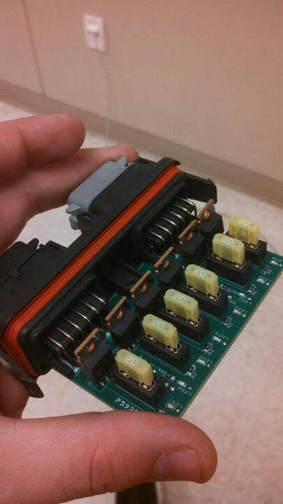
    Ours is currently just a re-dux of the previous board that I had made. In years past it had been relays and fuses, which worked great and was a step in the right direction but it was HUGE! All that I did this year was add some FET's instead and make things smaller.

    looks like this:


    In addition, it would be pretty easy to make it "less e-savy capable"(?). A lot of the options I'm thinking about are done via computer...like what you'd do with an ECU. With the option of either having input pins or over CAN, you could set it up just like a "dumb board" that would also have the protection features like current monitoring.

    DANGIT....if I don't have enough to do already....4 papers to write...and now you've got me going on this...ugh...i said i wasn't going to do this..

    and don't worry owen, you can keep all that black magic suspension stuff.
    South Dakota State University Alum
    Electrical/Daq/Engine/Drivetrain/Tire guy '09-'14

    Go big, Go blue, Go JACKS!

  10. #30
    Originally posted by jlangholzj:
    <BLOCKQUOTE class="ip-ubbcode-quote"><div class="ip-ubbcode-quote-title">quote:</div><div class="ip-ubbcode-quote-content">Originally posted by murpia:
    PWM control is an interesting topic. To do that requires a half-bridge electrical architecture not a simple high-side drive. You then have to deal with ground recirculation currents, so need a high current ground pin for the load as well as a high current supply pin. I'll have a think about that.
    before you get too far ahead of yourself with this one, the only time I'm aware that this would be necessary is if you're trying to drive a DC motor either direction...on command...and change that direction whenever you want.

    simple PWM control can be achieved with a high-side or low-side switch for fan speed and fuel pump regulation. </div></BLOCKQUOTE>
    I think you're confusing a half-bridge with a full-bridge. A full-bridge is needed for direction control. The half-bridge I'm referring to is simply either a single high-side driver plus a diode, a single low-side driver plus a diode, or a pair of drivers. The key point is that there is route for the recirculation current during PWM either through the diode or the other driver.

    Regards, Ian

+ Reply to Thread
Page 3 of 5 FirstFirst 1 2 3 4 5 LastLast

Posting Permissions

  • You may not post new threads
  • You may not post replies
  • You may not post attachments
  • You may not edit your posts