

Tim,Originally Posted by Tim.Wright

Yes, you are 100% correct.
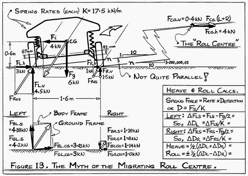
And, indeed, that is the way I had it on the original version of Figure 13 (shown below).
On the updated Figure 13 (several posts ago) I removed the body-reference-frame forces because I figured it was all getting a bit cluttered. Also, when looking just at the ground-frame force components, it is easy to see that the left wheelprint vertical force Fl.v = 4.5 kN (at top-left of sketch) equals the spring force Fgl.s = 4.2 kN, plus the control-arm vertical (jacking) component Fgl.ca x 1/10 = 0.3 kN (at bottom-left of sketch).
For control-arm stress calculations, decomposition of the forces in the body-frame is better. But, of course, any angularity of the real spring-damper (or its push/pull-rod) away from vertically above the wheelprint must also be factored into the calculations. As you have noted, a spring-damper that angles down-and-outward toward the wheelprint is beneficial in that it helps the control-arms by resisting some of the up-and-inward road-to-tyre loads.
~~~~~o0o~~~~~
As a further little twist, students might again consider the spring and control-arm forces in the body-frame (perhaps clearer in Tim's sketch, at left). The control-arm (or n-line) forces in this frame are horizontal wrt car-body-frame. Yet we should still expect the calculations for "jacking" effect to be the same as before, namely a Heave motion of about 12 mm. But horizontal n-lines CANNOT cause any jacking... So WT!!!???
The resolution to this problem comes from looking at the "body" forces Fg and Fi acting through the CG of the car. In particular, in the body-reference frame, Fg has a small leftward component, and Fi has a small UPWARD (!) component of ~0.4 kN, which, in effect, lifts the car ~12 mm
Z
 |

|


 Reply With Quote