+ Reply to Thread
Page 12 of 31 FirstFirst ... 2 10 11 12 13 14 22 ... LastLast
Results 111 to 120 of 303

Thread: Suspension Design

  1. #111
    Look guys, this really isn't that hard.

    Z is just advocating very simple systems for a very simple competition. The cars should posses these systems and no others (to keep it simple):

    A single cylinder engine

    A simple frame (preferably painted brown)

    A single speed transmission

    Longitudinally connected springs (help with bump capability)

    Diagonally connected springs (to stiffen in pitch and roll)

    Don't forget interconnectedly sprung left to right

    NO FANCY SUSPENSION, beam axles front and rear

    DIRECT actuating dampers that are cheap as dirt and don't work because you don't use them. The courses are smooth enough that you don't need to worry about wheel movement, but they are just bumpy enough that you need to spring all of the wheels together.

    Pull/push rods are unnecessary

    Suspension should be robust enough to enter the Baja SAE competition with

    An aero package capable of 3G on an autocross couse but still is rules compliant with less drag than a non aero car. (but aero also isn't considered a big enough deal to try to move dampers and springs out of the air stream).


    Remember guys, keep it simple.
    Kettering University Vehicle Dynamics
    Formula SAE 2010 - 2015
    Clean Snowmobile Powertrain 2012 - 2015

    Boogityland 2015 - Present

  2. #112
    @Z
    I've read a very large amount of the material you have posted on this forum and find nearly all of it useful and enlightening. However, you still haven't convinced me that push/pull rod suspension is 'complicated'. It's really quite simple! Just a couple of triangles with little joints on the ends. Put your dampers in your favorite spot, make a line from one of your triangles to somewhere in front of the damper, find the vector normal to the rod axis and the damper axis, and make one more triangle to rule them all!
    Plus, all of that math is something college freshmen can actually accomplish (with some guidance). In order to prove the beam axle setup you're designing is going to work @ +/- 1 in of travel before you build it, you're going to need some material classes under your belt, and you're looking at at least 2+ years into undergrad before than can even really be considered. Is a beam axle setup more simple than double wishbone... maybe. Is designing a beam axle that you can prove will work more simple than double wishbone? I do not think so, but perhaps in other schools they teach Mechanics of Materials before Calc III.

    @Markus
    Hey, we all know that in FSAE, the legs of the driver are included in the crush structure of the car. As long as your head and torso survive intact, you ought to be ok!

    @MCoach
    You know, Z knows a lot of things that are accurate and useful. His opinions on how to design as FSAE car... well they are opinions. Grain of salt: taken.
    Tennessee Tech Motorsports
    Project Manager
    facebook.com/TTU.Motorsports

  3. #113
    Senior Member
    Join Date
    Oct 2003
    Location
    Airports, A320\'s, 737\'s
    Posts
    310
    why not offer a team nearby, I guess in Australia, to coach them ..."[/i]

    Hmmm... So I have to find a very brave team, that is nearby, and is also prepared to mindlessly follow my advice...

    Then...

    "... even if "Monkey see, Monkey do" happens and all other teams start copying the winning concept...
    ... they will carry your thoughts into industry..."


    Without them having the foggiest idea of what they are doing!!!

    Tobias, how would the above improve the "education of young engineers"? (Please, no excuses... ).

    Rather than giving them a fish, I would prefer they learnt how to fish...

    Z
    There is a lot to be said about suspension design, and one's approach to fsae. However the only thing that I will add is that Tobias is improving the education of young engineers by volunteering his time as an organizer and a design judge. He is helping to create an opportunity for students to learn, understand and gain valuable experience. Tobias has (to my recollection) never instilled a singular path/solution to the fsae competition (and honestly, I don't know of any design judge who has). In my entire 12 years of involvement with the fsae community, I have never met any judge who has forced the status quo, or would not be interested in an alternative given sound engineering decisions and justification. I believe all the judges would and do encourage critical thinking over following the status quo.
    "Man, I need to practice more!" - Kenny Wallace
    "Try not to have a good time... this is supposed to be educational." - Charles M Schulz
    -OptimumG 2005-2006
    -Turner Motorsports 2008-2009
    -Black Swan Racing 2010 & 2011 Team and Driver's Champions
    -HPD Race Engineer 2011-2014
    -Currently Freelance Data/Race Engineer

  4. #114
    Senior Member
    Join Date
    Mar 2005
    Location
    Australia
    Posts
    1,690
    MCoach,

    You are overcomplicating it!

    Interconnected suspension is ONLY needed if the FSAE organisers ever get around to putting some real bumps on the track. You know, to encourage good suspension design...

    And diagonal U-bars are NOT recommended. Lateral and longitudinal Z-bars are enough. No more is needed (ie. no corner springs). In fact, it can all be done with one spring, but baby steps first...

    Otherwise, you seem to have grasped the concept.
    ~~~o0o~~~

    Still on the KISS theme...

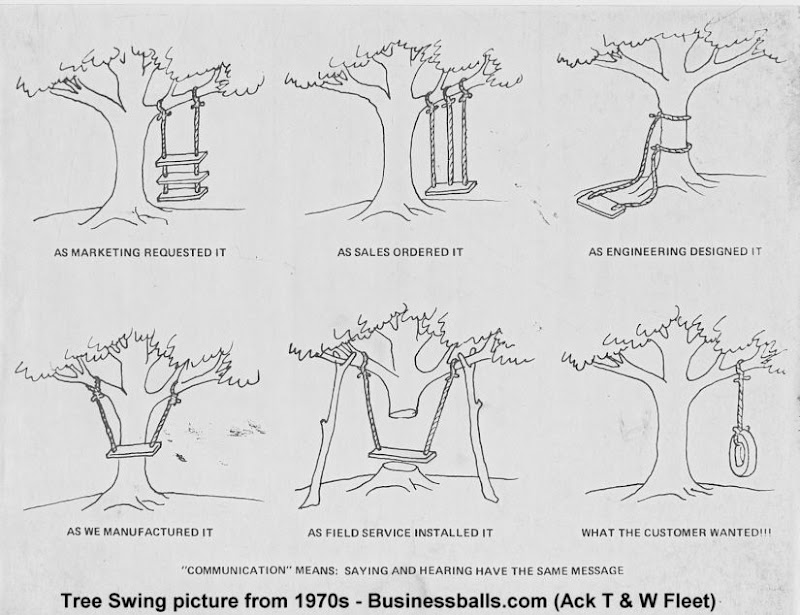
    A picture is worth a thousand words, so here is one that was in most drawing offices back when I started out.


    (I reckon Markus's team should build something like the mid-bottom picture, to protect Markus from himself. He does so love to crash into things! )

    A bit of background here. Short story, all engineering companies back then knew they were going to cock things up along the way, but at least they tried to keep the end goal in sight (even if it was just on a cartoon). I'm not sure that happens these days? Also interesting is that variations on the above cartoon mostly appear in software companies these days...

    My strong recommendation is that FSAEers should focus on the bottom-right picture, from first concept meeting all the way through to final testing and competition. I honestly reckon that way is the most fun. But that's just my opinion...

    Z

  5. #115
    Senior Member
    Join Date
    Mar 2005
    Location
    Australia
    Posts
    1,690
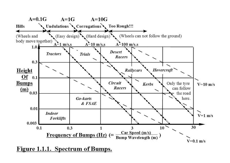
    Here is a picture of the "Bump Map" I mentioned earlier.

    As the figure number (1.1.1) suggests, this sort of map is the first thing suspension engineers should consider when laying out their design. The different types of vehicles (in italics) are shown roughly at the top right of the range of bumps they might expect to meet on typical tracks. They will likely all drive over hills (at top-left of map), but these don't effect the suspension. It is the bumps at the top-right of the vehicle's range (and how often they are encountered) that most determines the suspension requirements.

    The diagonal, dashed lines for maximum Velocity and Acceleration are based on hypothetical bumps of sinusoidal profile. Maximum velocity occurs halfway up or down the bump, and might correspond with damper velocity (depending on MR). Maximum acceleration is at the top and bottom of the bump. If the tyreprint, wheel, or whole car are not pushed down hard enough to match the required acceleration, then they leave the road at the top of the bumps.

    The "FSG bump" shown in Tobias's post (bottom page 5) is an "outlier" in FSAE terms (ie. rare, with possibly only one on the planet). It is probably halfway up the map on the "A=1G" line. As should be obvious, a suspension can only absorb a bump when the suspension has more travel than the bump has height. So a bump height of 10 cm requires at least 10 cm of suspension travel (double that is better). Hence an FSAE car with +/- 2.5 cm travel will necessarily get airborne over a 10 cm bump at the A=1G line. Well, unless it has aero downforce equal to its weight, in which case it stays on the ground up to the A=2G line.

    So, IMO, the above FSG bump is not a particularly good test of suspension (other than that the car should land without bouncing too much on its tyres...). A better test would be many bumps about 5 cm high, and between the A=1G and 10G lines, ie. between 3 to 10 Hz (where it says "Kerbs"). For an average FSAE speed of, say, 15 m/s (~54 kph), this means bump "wavelengths" of 5 m (gentler) to 1.5 m (harsher). Well designed, soft suspensions will drive over these bumps unaffected, while the stiffly sprung "real racecars" will launch ... (and crash???).

    Z

  6. #116
    Senior Member
    Join Date
    Mar 2005
    Location
    Australia
    Posts
    1,690
    Back on page 1 I tried to start a rational, big-picture, discussion of suspension design.

    There are many alternative, much simpler, and much more suitable suspension types that can be used [other than double-wishbones]. Very briefly, and roughly chronologically, the major suspension types are,

    1. Beam-axles (eg. on all vehicles ever, can be live or De-Dion at rear),
    2. Sliding-pillar (eg. Morgan and Lancia, and most motorbikes and aeroplanes at front),
    3. Lateral swing-axles (eg. Tatra (still on their trucks), can be high or low-pivot),
    4. Leading and trailing-arms (eg. Citroen 2CV front and rear, and most motorbikes at rear),
    5. Semi-leading/trailing-arms (eg. F100 at front, and many mid to late 1900s cars at rear),
    6. Strut-wishbone (eg. McPherson at front, strut at rear),
    7. Double-wishbone (eg. originally mostly at front to allow shorter wheelbase with front engine),
    8. 5-link (eg. recent fashion, mainly for NVH reasons).

    Of these, any of the first five are more than adequate for a winning FSAE car.
    ...
    The requirements of FSAE suspension are simple. They can be provided by any of the simpler suspension types.

    Rational criticism welcome.
    So far, IMO, the rational arguments have come mostly from those who have already tried the simpler approaches (eg. beam-axles and direct acting spring-dampers), and have been mostly favourable. Unsurprisingly, the negative arguments are mostly from those who haven't tried the alternative approaches. And rather than being rational, these arguments have a strong religious flavour, IMO.

    So, in the slim hope that there are at least some FSAEers out there who believe in reason over religion (and having covered Beam-Axles on another thread), let's move on...
    ~~~o0o~~~

    The SLIDING-PILLAR Suspension.
    ===========================
    This was the first independent suspension type widely used. Morgan used it on the front of its three-wheelers from before 1910, up until a few years ago (?). Lancia used it from the early 1920s (Lambda) to late 1950s (Aurelia). In both these cases the "evolution" from a beam-axle is quite obvious. The king-pin was simply lengthened and "sprung", thus allowing the wheel to both slide up-and-down, as well as steer. This suspension type is still common today (see below).

    I should stress that I would NOT use this type in FSAE. However, it is potentially a very minimalist design, so worth considering.

    Here are my (hopefully rational and objective) views of its pros and cons.

    Advantages.
    ==========
    1. Potentially the most compact type. All the suspension can be "inside the wheel".

    2. Puts minimal constraints on chassis design. A spaceframe would look similar to current cars, but the "triangles" going out to the wheels (= current wishbones) would be laid out to best suit the load paths to other important nodes, rather than having to suit the kinematics (eg. RC height, RC movement, etc.). And they would be welded to the nodes rather than requiring adjustable BJs, brackets, etc. A monocoque could be combined with a structural undertray that best suits aero requirements, and also happens to have four hardpoints at the corners (to which are bolted the sliders).

    3. The kinematic wheelprint n-lines have constant slope wrt chassis, giving predictable handling. These slopes can be adjusted by "shimming" the slider mounts. Vertical sliders, and hence horizontal lateral and longitudinal n-lines (= ground level "roll and pitch centres"), is a good place to start.

    4. Can easily be arranged to have zero bump-steer (see below).

    Disadvantages.
    ============
    1. The sliding surfaces necessarily have much higher relative velocities than those seen in the joints of wishbones or swing-arms. This means that any "stiction" at the sliders is more acutely felt as harshness in the suspension. This is the main reason I don't like these types, and probably why they are so rare in nature. However, the stiction problem can be overcome by "linear roller bearings", readily available at your friendly local bearing shop.

    2. A straight slider gives zero camber gain/compensation. This means that any body roll gives an equal, and adverse, amount of undesirable wheel inclination. About half of all FSAE cars currently have similar kinematics (ie. very long front-view-virtual-swing-arms), so clearly not a big problem (ie. roll countered by stiff ARBs). A curved slider can be used to solve this problem, but that can get expensive. Incidentally, the Morgan and Lancia kinematics have a vertical ISA at the centreline of the cylindric slider, with the steering-rod giving a very long screw pitch, and hence small bump-steer.
    ~~~o0o~~~

    The above probably makes more sense if you have some idea how this could be done in FSAE.

    So, perhaps a 16mm diameter shaft, ~200+mm long, fixed top and bottom to the corner of your chassis. The ~150mm tall upright both steers about this "kingpin", and can also slide up-and-down it, giving the +/- 25mm travel. Bronze bushes (cheap and compact, but with stiction) or linear bearings (low friction, but bulkier) can be used for the sliding surfaces. A conventional steering/toe-link from the centreline of the car can be used to control toe-angle, with negligible effect on handling from the small bump-steer. Incidentally, hardened and ground round shafts, optionally hard chrome plated, are readily and cheaply available from bearing shops or hydraulic suppliers.

    Alternatively, two vertical shafts through the upright could be used (one in front, and one behind the wheel axle). These would be connected top and bottom with motorcycle style "triple-clamps". These clamps would be bolted to the chassis for the rear wheels, but would have their own steer-axis at the front (= easy zero bump-steer, since suspension is "outboard" of steering).

    Or an "inside-out" arrangement would be a suitable match for the Amberg-Weiden car (ie. odd wheel bearings with similarly odd suspension). The vertical stiffener inside AM's ringlike wheel-hub could be replaced by the above round bar slider, and this would slide and steer inside a bracket bolted to the chassis.

    Springing and damping can be added in any number of ways. But remembering that "zero-suspension-movement" cars have won FSAE before, perhaps just some rubber bungy straps, assisted by PU-foam bump-rubbers, could be used. Or you could complicate it...
    ~~~o0o~~~

    So, has Z totally lost it on this one? Is any of this nonsense even feasible???

    Well, almost all motorcycles today use "sliding-pillar" front suspension. Most pre-WWII bikes with rear suspension started with these. Interestingly, most pre-WWII motorcycles had a form of double-wishbone front suspension (= 4-bar-linkage "girder forks"), but those were eventually ditched...

    Almost all nose wheels on aeroplanes, from small Cessnas to 500+ ton super-jumbos, use a sliding-pillar. Many of the main wheels on these aeroplanes are similarly sprung.

    Many ~500+ ton mining trucks use these at the front, again for both suspension and steering. Typically they use a ~0.4+ metre diameter shaft, several metres long. The stiction breakout force used to be measured in TENS of tons, but nowadays hydrostatic bearings reduce that to, oh..., only about a ton. One of my tractors also has them, again at front. So far completely reliable, and quite effective.

    So for the very small number of FSAEers who hope to get jobs in motorsport, perhaps you should stick with wishbones. For rest of you who might get jobs working on motorbikes, aeroplanes, mining trucks, tractors, or whatever, you just might have to learn about this suspension type eventually.

    Z

  7. #117
    Senior Member
    Join Date
    Mar 2008
    Location
    Buffalo, NY USA
    Posts
    340
    Originally posted by Z:
    The SLIDING-PILLAR Suspension.
    Here's a technology demonstrator (trade show attention-grabber) with updated sliding pillar front suspension, inside large diameter wheels:
    http://autos.sympatico.ca/feat...gy-meet-pre-war-ford
    As noted in the video, a hot rod was chosen because the suspension is exposed. A more practical application mentioned in the video could be the rear axle on a minivan...very low floor height.

  8. #118
    Very interesting Doug, especially how the bump steer problem has been solved, but where are the springs ??
    Cheers, Tony

  9. #119
    Originally posted by Warpspeed:
    Very interesting Doug, especially how the bump steer problem has been solved, but where are the springs ??
    They were moved to the firewall using a hydraulic system.

  10. #120
    Senior Member
    Join Date
    Aug 2009
    Location
    Kannapolis, NC
    Posts
    382
    From the depths of the forum (aka, 2004)


    And Z, you make some good points, but at 3-10 hz, you're basically just saying use rumble strips instead of cones. If you want anything above that height, there's another competition for that. It's called Baja SAE.
    Any views or opinions expressed by me may in no way reflect those of Stewart-Haas Racing, Kettering University, or their employees, students, administrators or sponsors.

+ Reply to Thread
Page 12 of 31 FirstFirst ... 2 10 11 12 13 14 22 ... LastLast

Posting Permissions

  • You may not post new threads
  • You may not post replies
  • You may not post attachments
  • You may not edit your posts