+ Reply to Thread
Page 2 of 3 FirstFirst 1 2 3 LastLast
Results 11 to 20 of 21

Thread: Upright Weights

  1. #11
    Upright stiffness is just a part of the puzzle. You need to look at how it plays into your total camber/toe compliance. And if you've haven't measured the actual, physical compliance of your bearings, then you're guessing on a big part of the picture.

    If you want less unsprung mass, run 10s!
    "Gute Fahrer haben die Fliegenreste auf den Seitenscheiben."
    --Walter Röhrl

  2. #12
    Senior Member
    Join Date
    Aug 2005
    Location
    Grand Rapids, MI
    Posts
    284
    I am 100% in agreeance with you guys which is why I mentioned displacement results from FEA analyses. I know this isn't the best way to quantify stiffness, but it's a quick and easy way of showing how much the upright will flex under full loading. The optimization work I've been doing has focused completely on minimizing weight and maximizing stiffness - I've never overlooked the importance of stiffness. The bearing question is definetely something I juggled, but ultimately decided to leave out of the picture as its effects on the topology analysis most likely won't alter the synthesized candidate design (it's just a null element from that standpoint). Thanks for all the input and mass numbers, they will be very helpful for my paper.
    Conor Riordan
    Lincoln Design Judge 2013
    Michigan Design Judge 2012, 2014
    Notre Dame 2009
    WMU Team Captain 2008

  3. #13
    I have some info on our 2007 front upright from an old report. Weight was around 800g, 4130/4140 steel TIG welded, I think the bearings were 90mm OD.

    FEA results under 1.7g cornering plus 1g braking loads, max deflection 0.32mm on a caliper mount, max 0.18mm approx in the spindle area. No idea what that corresponds to in toe or camber deg/g change, it was a while ago and I'm only reading this off an image...

    In 2008 they were similar design but smaller and lighter, same stiffness I believe. Don't quote me on this but I think they got down to 600-650g or so.
    --------------------------------------------
    Technical Director UARC 2007

    http://formula-sae.adelaide.edu.au

  4. #14
    CNC'd 7050 Al, camber deflection of 0.13 deg/g.

    Front: 1.25 lb (566 g), 2.56 in. (65 mm) bearings

    Rear: 1.38 lb (625 g), 2.72 in. (69 mm) bearings
    Dr. Adam Witthauer
    Iowa State University 2002-2013 alum

    Mad Scientist, Gonzo Racewerks Unincorporated, Intl.

  5. #15
    <BLOCKQUOTE class="ip-ubbcode-quote"><div class="ip-ubbcode-quote-title">quote:</div><div class="ip-ubbcode-quote-content">Originally posted by Conor:
    I am 100% in agreeance with you guys which is why I mentioned displacement results from FEA analyses. I know this isn't the best way to quantify stiffness, but it's a quick and easy way of showing how much the upright will flex under full loading. The optimization work I've been doing has focused completely on minimizing weight and maximizing stiffness - I've never overlooked the importance of stiffness. The bearing question is definetely something I juggled, but ultimately decided to leave out of the picture as its effects on the topology analysis most likely won't alter the synthesized candidate design (it's just a null element from that standpoint). Thanks for all the input and mass numbers, they will be very helpful for my paper. </div></BLOCKQUOTE>

    Thats quite similar to our 2007 upright, same type of design around 2lbs weight, ~0.006" deflection at bearing seat/spindle area for 2g cornering and 2g bump. 60mm OD bearing
    Finished @ UofT Racing
    2003-2007
    www.fsae.utoronto.ca

  6. #16
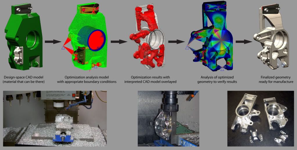
    Conor, it sounds like you're driving OptiStruct in the right way - use a mass constraint with a minimum WCOMP response as your design objective. This will produce the stiffest structure for a given mass, though be careful of the pitfalls. You should include a rigid suspension to properly feed loads into your part (constrained at the inner ball joints) - make sure it's rigid though. Otherwise OS will try to create structure to stiffen the kinematics (your whole part moves, and that looks like a lot of compliance to OS). The other flaw is that the solution is mesh-dependent unless you have a _very_ fine mesh. OS will never create sheet metal structures and it's minimum member size is limited by mesh density. Be sure to use TET10 or HEXA8 elements to get a reasonable stiffness result. If you find that your solution is driven by mesh size, then re-mesh more finely with TET4's and hope for the best. I've found that you need a monster compute machine to solve a finely meshed TET10 upright...though luckily at the time I had access to one...(32 Gb memory per compute node)

    You can also include stiffness constraints on the upright to push the optimizer towards the right part. We used toe and camber stiffness constraints that we determined from tire data and the upright's contribution to the total compliance (springs in series). I'll leave it up to you to figure that part out...

    I believe our 2006 uprights were in the 6-800g ball park.

    GK

  7. #17
    Cool, I actually was never even aware of OptiStruct. Learn something new every day.

    For ours, I just wrote a genetic algorithm that determined the dimensions based on a 75 DOF segmented-beam model. Sort of a ghetto-FEA, but in the end the results matched fairly well to COSMOS.

    Run time in Matlab was around 2 hours on my good ol' Athlon 64 3800+. It was a good bit of work, but it was my final project for our ME dept's optimization class. Was a very interesting project, I learned a lot.
    Dr. Adam Witthauer
    Iowa State University 2002-2013 alum

    Mad Scientist, Gonzo Racewerks Unincorporated, Intl.

  8. #18
    This years front uprights are about 450g. Don't know about the stiffness, but hollow-cast aluminium structures should't be that bad.
    I believe, if they look at the caliper position and the resulting load paths and tune the FEA simulation to be more accurate about how the bearing forces are fed into the uprights, there could be an upright possible with about 350g - 400g without loosing much if any stiffness.

    Using magnesium would probably save you another 50g - 100g. Because of the limitations of the casting process we cannot manufacture an upright with wall-thickness below 2.5 mm, even if that much material isn't needed there. Unfortunately we haven't found someone who is able to cast our uprights out of magnesium.

    Jost

    Wheel-Assembly '07
    Lions Racing Team Braunschweig

  9. #19
    I would caution everyone running independent component optimization not to spend too much time chasing that last 10% stiffness. You will find that the real-world gains are minimal for the effort you put into it.

    Get your part to 90% and then run a complete assembly analysis of the suspension, from a-arms to the wheel rim. When you have that many parts acting in series and parallel you will find that getting one part almost infinitely stiff compared to something as flimsy as most of the spun wheel shells used in FSAE is a fruitless exercise.

    Remember, the SYSTEM needs to meet a target and that will be limited greatly by the weakest member in the link.

    Example: A featherweight upright gives 0.15 deg/g toe compliance. You want half that, so you spend days and add 15% weight to the part to cut the UPRIGHT COMPLIANCE in half. Then you run a full assy sim and find that the compliance has only gone to 0.14 deg/g. Did you really spend your time and weight budget wisely?

  10. #20
    These are form the last UC San Diego car. They were designed (using OptiStruct) and manufactured by Billy Wight who posts on here occasionally. Not sure of the weight and stiffness numbers but maybe he will chime in. They were pretty damn light though as they were AZ31B-H24 magnesium and packaged inside 10" wheels.


    Bearings we used were a setup a la Carroll Smith: needle bearing to take the radial loads and deep groove inside to take up the axial loads. For the front we used a SKF HK 5022RS needle (.076 kg) with an inner race IR45X50X25 (.0708 kg) and a SKF 61908-2RS1 (.12 kg) deep groove. For the rear, INA NK85/25 needle (.425 kg) with an inner race INA IR75X85X30 (.287 kg) and a SKF 61815-2RS1 deep groove (.150 kg). Never got a chance to test the stiffness of the bearing assembly though.

    Here is a link from Billy's website for uprights he did for Stohr. It is a good description of the design cycle with OptiStruct.

    http://www.luxonengineering.co...sme_presentation.pdf
    Damon Lemmon
    UCSD FSAE
    Triton Racing 2005-2008

+ Reply to Thread
Page 2 of 3 FirstFirst 1 2 3 LastLast

Posting Permissions

  • You may not post new threads
  • You may not post replies
  • You may not post attachments
  • You may not edit your posts