+ Reply to Thread
Page 1 of 2 1 2 LastLast
Results 1 to 10 of 11

Thread: Adams/Car template updates

  1. #1
    For kicks I took a look at the FSAE A/Car templates supplied by MSC. First, thank you to MSC for supporting FSAE and the students. What I found was the templates date back to Adams version 11.0 and other than the powertain they have not had any topology updates. For students (novice adams users) these templates would be frustrating to use or unusable.

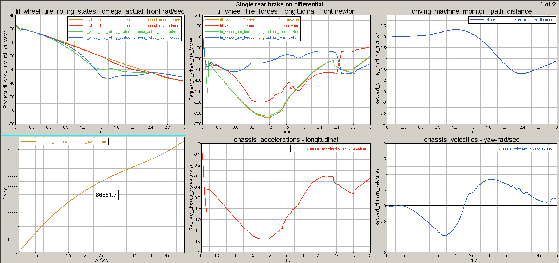
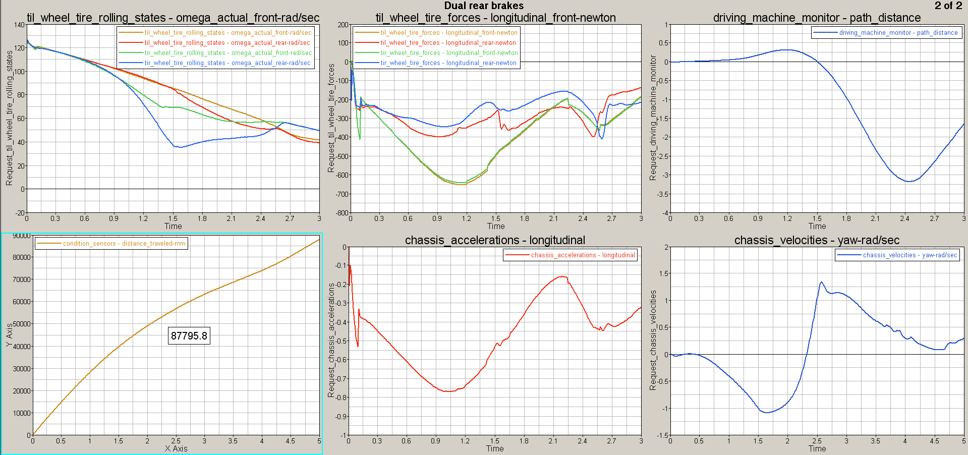
    I've started to weed-out some the "gotchas" and create some new templates that are more representative of a Formla SAE car topology (single rear brake, chain drive, t-bar swaybars etc..). I'd like to hear from anyone that has done similar work, so that I can incorporate those ideas.

    I am currently working with 2005 R2. I will wait until the 2005 R2 templates are completed before moving the templates over to MD R3.

    John Burford

  2. #2
    Here's a little teaser.

    This is an example of how Adams/Car can help make design decisions for the teams willing to develop simulation capabilities. Over the years there has been some debate is to which is better a single brake on the rear differential or two brakes at the rear wheels. Here is how simulation can help guide your decision. The following is a brake and turn maneuver. The maneuver was run for both brake configurations. The metrics that look interesting are; longitudinal acceleration, path distance (path error), distance traveled over time, and yaw rate.

    Single brake

    <span class="flash-video">http://www.burford-eng.com/public/single_brake.avi </span>

    Dual brake

    <span class="flash-video">http://www.burford-eng.com/public/dual_brake.avi </span>

    I interrupt the results in the following manner:

    1. The torque biasing of the diff allows for more total braking (while turning) as evident by the longitudinal acceleration plot.
    2. The single brake configuration produces a better (smoother) yaw rate curve. Although, the torque biasing workings against the turning direction. To much torque biasing (similar to a spool) forces the car to push into the turn despite achieving greater de-acceleration.
    3. The better yaw rate also produces less path error of 1.5m; potentially more stable handling.


    This is how simulation can offer great value to your design. The alternative is to design both into your car and try them out. Given the weight, cost, and time penalties I would find it unlikely any team tries to answer this design question through testing.

  3. #3
    I'm posting the models used to create the brake and turn analysis. I hope to hear from students on how they are using these models to develop their designs. Please post any interesting conclusions, or suggestions for additional features.

    http://www.burford-eng.com/public/FSAE_templates.ZIP

  4. #4
    Good job, too bad I'm using 2010.I would be willing to bet most teams are at least up to R3 by now.
    All of my older R3 stuff runs fine in 2010, any idea what would be involved with converting from R2?

    Regardless, thanks for the great design study example.


    As far improvements to my template model:

    -Added some missing force requests at certain locations

    -Made ARB subsystems kinematic (by default the bushings are always active and will cause inaccurate anti-roll rates)

    -Made a figure 8 road profile to skip pad event dimensions, hopefully will be adding slalom and a autox-style profiles in the near future

    -I'm working on a chassis subsystem with torsional spring[s] for stiffness studies
    Joseph Little
    Chrysler Group LLC
    CAE/Vehicle Dynamics Tools Development
    Mississippi State Motorsports Alum 2008-2010
    Get Adams/Car, the FSAE Database, and Training Materials:
    www.mscsoftware.com/fsae

  5. #5
    Joseph

    I converted the templates to MDR3. Primary reasons being the GSE based powertrain and more analysis choices.

    -What force requests were you interested in reviewing?

    -For ARB, set the TZ bushing data to zero(no inaccuracy in rate that way).

    I converted the VI-Grade track profile to xml format for limit handling events. Use "file driven events" analysis and select Track_Full.xml for the event and Autocross_3d_road.xml for the road profile.

    I have a mnf file of the chassis for torsional stiffness. It is a much easier approach as apposed to splitting the chassis into two parts and re-associating the suspension joints and bushings.

    These files are available on my web site at the same location as the database zip file.

    Autocross_3d_road.xml
    f98_003_9_flex_0.mnf
    Track_Full.xml

  6. #6
    -Your ARB solution:
    Easier than what I did

    -Your Road File/DCF
    Looks great, I'll give it a try soon

    -Your flex chassis:
    As far as I know a MNF can't be parametrized for design studies, but I can still believe generating a set of MNF could be easier than the rebuilding the I/O communicators

    Which program did you use for generating the MNF?
    Joseph Little
    Chrysler Group LLC
    CAE/Vehicle Dynamics Tools Development
    Mississippi State Motorsports Alum 2008-2010
    Get Adams/Car, the FSAE Database, and Training Materials:
    www.mscsoftware.com/fsae

  7. #7
    I use HyperMesh for FEA work. The MNF is a simple model using beam elements (PBARL specifically). The node locations and beam elements can be imported into HyperStudy and run as a DOE or optimization. The idea is to separate the structural investigation from the multi-body dynamics simulation.

    If you are studying the effect of torsional stiffness on handling events, I would create a couple of MNFs. Change the Modulus of Elasticity by some percentage for each MNF generation run. It should take only a couple of minutes change the deck and rerun. Look for “MAT1” and change “210000.0” to some percentage of the original number.

    Mesh only
    f98_003_9_flex.fem

    MNF creatation
    f98_003_9_flex_prp.fem

    These are the FEA models for the MNF

  8. #8
    Thanks, I didn't know Hypermesh could do MNFs. I believe I know some people who use the program who can help me out. I have been trying to use Nastran/Patran and just can't find up to date documentation/examples.

    I noticed that you work for Honda R&D, I may get to work on a project with one of your suppliers using a ADAMS model you guys created. Not sure though, my professors seem to change their mind about what they want me to work on daily...
    Joseph Little
    Chrysler Group LLC
    CAE/Vehicle Dynamics Tools Development
    Mississippi State Motorsports Alum 2008-2010
    Get Adams/Car, the FSAE Database, and Training Materials:
    www.mscsoftware.com/fsae

  9. #9
    Creating a MNF from a Nastran deck is fairly easy. Remove any "subcase" or "method" cards from he deck. Renumber all Craig-Bampton nodes starting at 1001 and renumber the rest of the nodes in the model starting with 2001. This leaves 0-1000 empty for scalar points. Edit this deck head to have you Craig-Bamptom nodes in the ASET and set the "include" file name to be the bulk data file with the renumbered nodes.


    $
    SOL 103 $ nastran modal analysis
    $
    CEND
    $
    TITLE=Generate MNF file
    $
    ECHO = NONE
    ADAMSMNF FLEXBODY=YES,PSETID=2
    RESVEC=BOTH
    WEIGHTCHECK = YES
    $ Subcase 1 control
    SUBCASE 1
    METHOD=1 $ to define EIGRL card (eigenvalues calculation)
    $ Elements for sketch file
    OUTPUT(PLOT)
    SET 2 = PLOTEL $plot elements for sketch
    $
    BEGIN BULK
    PARAM,COUPMASS,-1
    PARAM,K6ROT,1.0
    PARAM,PRGPST,NO
    PARAM,AUTOSPC,YES $ to fix singularities problems
    PARAM,GRDPNT,0 $ to debug mass matrix in the f06 file
    PARAM,POST,-1
    $
    DTI, UNITS, 1, MGG, NEWTON, MM, SECOND $ assigns units for ADAMS
    $
    $------12------23------34------45------56------67------78------89------9
    EIGRL 1 15 MASS
    $
    $ define dof to use for modes
    $
    SPOINT,1,THRU,1000 $ include one scalar point for each CBP dof and mode on EIRGL card
    $
    $______________ASET_QSET__________________________ _____
    $------12------23------34------45------56------67------78------89------9
    QSET1 1 THRU 1000
    $ set 6 dof for CB points
    $------12------23------34------45------56------67------78------89------9
    ASET1 123456 1001 1002 1003 1004
    $
    $----------------------------------------------------------
    include 'lower_arm_RH.dat'
    $----------------------------------------------------------
    ENDDATA

  10. #10

    Flex chassis

    Hi Jhon,

    I´m currently working in building a model of a FSAE that includes the frame of the car as you were talking. I already have the MNF file of the frame but i´m having trouble connecting it to the full vehicle assembly. I downloaded the database that you posted but i do not see the flex chassis there. Can you help me uploading the full vehicle assembly with this flex chassis so i can guide to build my own?
    Thank You so much

    Juan Gomez
    Universidad de los Andes, Colombia

+ Reply to Thread
Page 1 of 2 1 2 LastLast

Posting Permissions

  • You may not post new threads
  • You may not post replies
  • You may not post attachments
  • You may not edit your posts