+ Reply to Thread
Page 7 of 28 FirstFirst ... 5 6 7 8 9 17 ... LastLast
Results 61 to 70 of 277

Thread: Beam Axles - Front, Rear or both.

  1. #61
    Rob Woods is back! Too many posts on one of your favorite topics and no reply in a week or so- I was just getting worried... F500's are so neat small and simple machines, that could make a hell of a "beginners car" in FSAE. (adopted to the rulebook) The only thing I doubt of is the CVT, and I doubt because I have never dealt with one, so in my mind they are just heavy, complicated, hard to work things that make your engine sound funny...

  2. #62
    Senior Member
    Join Date
    Sep 2004
    Location
    Rochester NY
    Posts
    1,061
    I was out of town and busy after that. Check out this post and videos.

    http://fsae.com/eve/forums/a/t...20489051#51220489051

    A F500 has a worse weight to power ratio, no hydraulic dampers only polymer pucks for springs AND dampening, 20 inches more minimum wheelbase, not allowed to run wings or tunnels so only really a diffuser and a 800lbs minimum weight and it ran within a couple tenths of RIT FSAE most recent car. They are terribly handicapped in every respect to a modern competitive FSAE car yet run times that are very close to competing for a win. It's ALL in the CVT. Imagine a 60 inch wheelbase(instead of 80 inch), 350lbs car (instead of 800), with a weight to power ration of 7:1 (instead of 10:1), suspension designed to integrate aero (instead of mandated suspension design), with a well tuned CVT and you can see how that would make up for a couple tenths and much much more. If you could integrate a polymer puck instead of hydraulic damper with spring you can save 5000 on the cost report. Ditch the diff and halfshafts for a solid axle and save an additional 3000. You can easily win cost and sales presentation. The possibilites for a cheaper yet more effective win are there because otherwise you wont be able to out resource (talent,funding,knowledge,facilites,etc.)a team like Oregon unless you are an elite few (maybe 20 teams).

  3. #63
    Well, if you notice, I have commented a great deal in the above posted thread.... I did not say CVT's are no good (in fact I like your approach a lot) but I have not dealt with them even a little, so it's "black magic" to me, so no CVT for my car (as stated in the "objectively" thread, single cylinder with 3 gear transmission). I think I'm waaaaay offtopic now though!

  4. #64
    Senior Member
    Join Date
    Sep 2004
    Location
    Rochester NY
    Posts
    1,061
    I noticed Harry. Threw that one out to tie back to the other topic for the uninitiated.. They aren't all that big and scary. They are less complicated that learning a fuel injection system and that is something all teams have to go through.

  5. #65
    Senior Member
    Join Date
    Feb 2004
    Location
    Costa Mesa, CA
    Posts
    773
    Originally posted by rjwoods77:
    I would like to hear the rationale as to why this has to be an open wheel format and the purpose behind it.
    If it's anything like the rule about the restrictor location within the system, it's still there because they think it's both "challenging" and "for safety." I'm sure if you pressed the issue that you would get an earful about how allowing for a closed body would make it too easy to generate downforce and how that would somehow lead to the cars becoming too dangerous to drive. I got the same argument when I pressed the restrictor location thing. There was also a heavy dose of "tradition" thrown in when I pressed the restrictor issue (which I also thought was silly). I'm sure they would also feel the "formula" part of Formula SAE would be gone if they weren't completely open wheel cars anymore.

    As long as there is a clearly defined spec, I think it's fine to do whatever they want. I hope that the rules committee will quickly address the apparent hole in the "open wheel" issue. The rules say something to that effect in the beginning, but then there's no written definition of what that actually means!

    -Kirk

  6. #66
    I know shit about fuel injection too... You are right that this is part of learning though. The thing is that despite my "fear for the unknown", all current FSAE engines have gearboxes; a CVT is more extra weight. So, possible solutions:
    1) Replace gears with axles, bolt CVT; straightforward but heavy
    2) Machine a new crankcase with no GB and built-in CVT; hard on resources, easier for singles (ball-bearing bottom end, simpler lubrication, split stock crankcase)
    3) Electric drive; far from simple, a bit heavy compared to singles, expensive, but lots of torque, direct drive, more powerful than any 4-cyl.

    In fact we are going no3. this year (and this was a decision of our faculty which in first did not like). I know that this seems way off the "simple" way, but I assure you that our car is gonna be simple as hell; direct drive from the motor (no reduction), no torque vectoring so a simple powertrain, components and mainly batteries placed for minimum Iz. The thing is that I have a hard time convincing our faculty to go "low tech" (beam axles), especially now that we spend a lot of money to go "high tech" (electric)... The good thing is that I like this way so much, that I have already made tons of research on my own. Actually I will have some of our team members do some quantitative analysis on gains/losses on a "beam axle" car, but after the exam period is over, which I will post around here for reference (unless we decide to go that way after all...:P)

  7. #67
    Senior Member
    Join Date
    Sep 2004
    Location
    Rochester NY
    Posts
    1,061
    Funny you mention electric. I was thinking the other day how easy it would be to make a double beam car with a pancake motor in each wheel.

  8. #68
    (Just edited above post). OR wou could make a 4WD electric car, benefiting from aggresive regenerative braking to cut down battery pack size and use a well-tuned torque vectoring system to aid vehicle dynamics... I will have my eyes open for Delft this year, they go 4WD and they cut down their battery pack about 13kg (per my calculations based on data about their new batteries), so it might get interesting!

  9. #69
    Senior Member
    Join Date
    Mar 2005
    Location
    Australia
    Posts
    1,690
    Some comments regarding:

    AERO
    =====

    (Rob Woods quote)
    "It seems that aero balance was the reasoning behind splitting the aero into front and rear underwings."

    Rob,

    Yes, the Twin Beam-Wing is intended to give maximum aero performance for minimum effort, which includes minimum understanding of aero. This means easy set up of, and stable, F/R balance. Hence the two wings with their separately adjustable flaps and downforce. There will be some inevitable interactions between the two wings, but hopefully easily managed. More downforce is possible (from full undertray) but that requires better aero understanding, especially regarding F/R balance.

    IMO the Herb Adams' Catamaran-Wing-Car in your links likely suffered from excessive pitch sensitivity of total DF and F/R balance. Even with rigid suspension and a perfectly flat road any slight nose-down pitching, say from tyre squash, brings the nose splitter closer to the road, which creates a thoroughly "unsteady" flow condition, which first increases front DF, but then the suction travels further back ('cos unsteady), etc., all of which is a killer for predictable handling.

    Incidentally, the smooth upper-body surface possible with the catamaran layout is not necessary for good aero DF (although maybe a small advantage for low drag). A wing can only have a maximum Cp=+1 on its pressure surface, while Cp<-10 is possible on the suction surface. A similar 10:1 ratio applies over the whole surfaces. Bottom line is that the top surface of a racecar is of little importance to DF, because all the action is underneath (with some qualifications ). A good example is military aircraft that have a dog's breakfast of bombs, missiles, fuel tanks, etc., stored on the pressure side of the wing, but rarely anything on the suction side.
    ~~~o0o~~~

    The best way to deal with aero balance problems is via the aero design (ie. as noted above, even rigid suspension and flat roads can't fix some problems).

    Nevertheless, you ask,
    "Also minimizing individual movements of the suspension modes (i.e. interconnected suspension) to keep the aero consistent in general but especially if it was a single aero element...
    Could you discuss the application of an interconnected suspension in terms of benefiting a pure aero performance driven design."

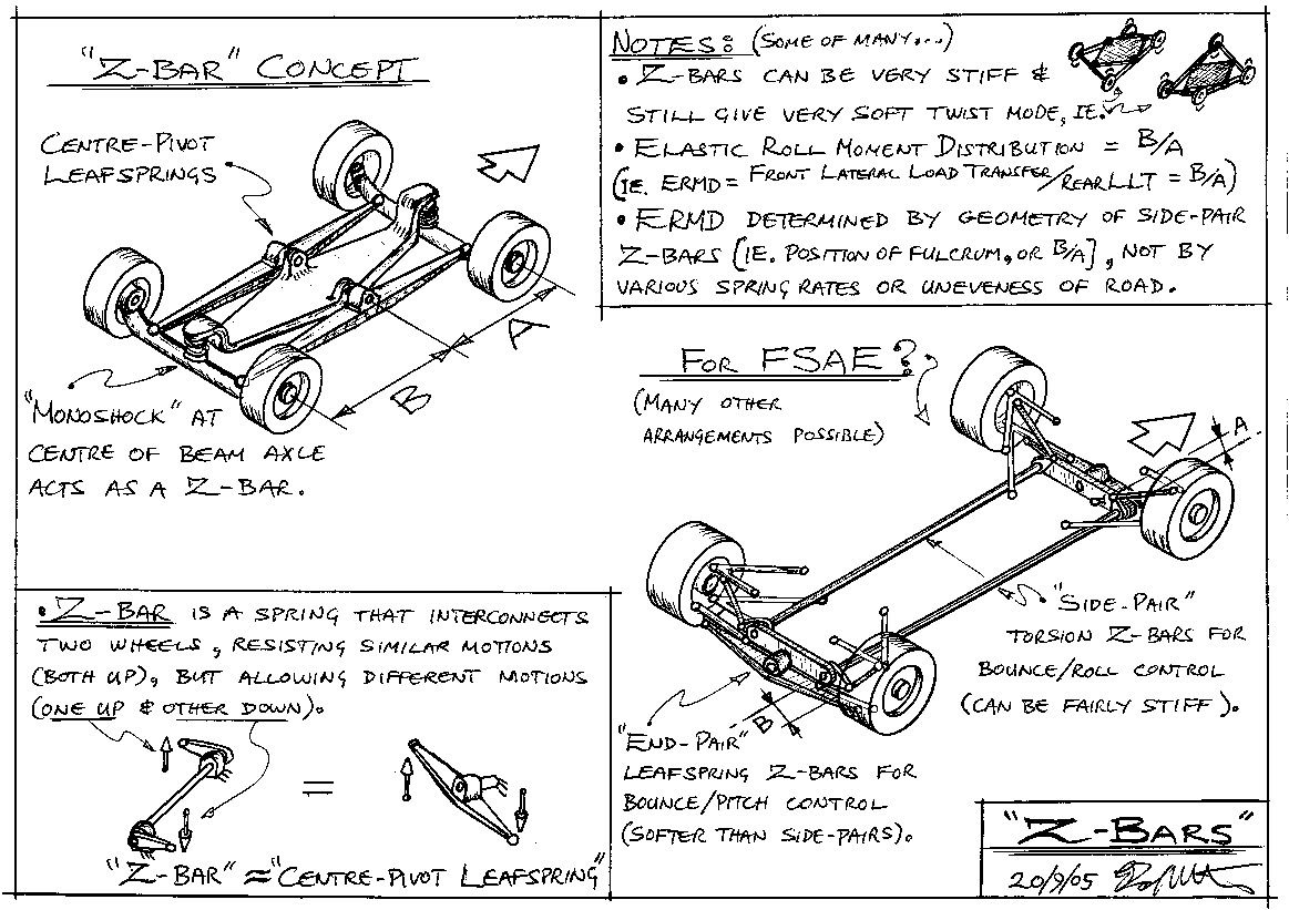
    Conceptually, the best way to have a single rigid aero element and keep it at a consistent height and attitude above the road surface, is as shown at top left and right of the Z-Bar sketch (redisplayed below). This is perhaps best understood in the top right sketch where the diamond shaped structure (say the aero element) is positioned relative to the uneven road surface such that its two side-points are at the average height of the two side-pairs of wheelprints, and its two end-points are at the average height of the two end-pairs (axle-pairs) of wheelprints.

    Strictly speaking, these sketches are over-constrained. The diamond structure only needs three of its corners attached to the mid-points of three of the "balance-beams" (or "averaging-lines") that interconnect the four wheels. This three-point support (like a tripod) controls the diamond's heave, pitch, and roll motions. The symmetry of the four point support helps with understanding, and is better structurally (better distribution of loads).

    Many different practical implementations are possible, but something close to the top left sketch, though with lightweight and rigid Side-Pair-Balance-Beams instead of centre-pivot-leafsprings, and BJs instead of coils at the beam-axle centres, would work. The SPBBs could do double duty as beam-axle locators. The chassis would then sit on four soft coil springs arranged in a diamond pattern on the centres of the 2xBeam-Axle+2xSPBB substructure.


    (RW quote)
    "Could the A/B ratio in such a scheme I described be somehow used to balance front to rear aero forces conducted into the unsrpung mass through that interconnection?

    No. The resultant of the aero pressures (ie. the aero "force screw") is always equal and opposite to the resultant of its reactions from the four wheelprints. Any contrived linkage between these "equal and opposite" forces cannot change the F/R aero balance. However, the linkage can change the distribution of the front DF acting on the two front wheels, and hence necessarily also alter the distribution of DF acting on the two rear wheels.

    This is similar to a given cornering force always giving the same total Lateral Load Transfer from one side to the other, although the distribution of this LLT between front and rear wheels can be varied.
    ~~~~~~~~~~~o0o~~~~~~~~~~~

    SUSPENSION LINKAGES
    ====================

    (RW quote)
    "In my concept I wanted to use a front and rear mumford link ... to connect a pair of torsion z bars front to rear"

    That could be done, BUT (!!!) it is important to remember that the ends of the Z-bars MUST BE bent in opposite directions (otherwise it is a U-bar). So, picturing an end view of the linkages, if the front Mumford rockers are in their "normal" orientation, then the rear rockers MUST BE upside down. This puts one set of rockers quite low down, and may cause problems with ground clearance. Some draft layouts would be necessary to see if it can all be fitted into the space available.

    Note that for FSAE or F500, the lever arms at the ends of the Z-bars only have to be about 2" long to give adequate suspension travel. In terms of stresses, the Z-torsion bar could be about 1/2" diameter 4140 steel (x wheelbase length), or even thinner if using proper spring steel.
    ~~~o0o~~~

    (RW quote)
    "would the beam axles then act as an theoretically infinitely stiff "end-pair" leaf springs"

    No. The Mumford link rigidly constrains axle-lateral-motion relative to its virtual RC, while offering no resistance to axle-roll about that point, or axle-bounce (=axle-heave). So you would have to add a central coil spring, between beam and chassis, to control axle-bounce. It is possible to control axle-bounce with non-linearities of the Z-bar lever arms (eg. by giving them rising rates), but that might introduce other problems (eg. non-linear LLTD).
    ~~~~~~~~~~o0o~~~~~~~~~~~

    DAMPING
    ========

    (RW quote)
    "F500 cars are mandated by rules to not run hydraulic dampers of any sorts. They are forced to run polymer pucks ...
    If an interconnected double beam could utilize polymer dampers it would easily cut 5000 dollars off the the cost report ...
    Please comment..."

    The main point I was making on the "Damper Histograms" thread was that the importance of dampers is highly over-rated. Expensive (eg. 4-way adjustable) dampers are "crutches" for badly designed suspensions, namely suspensions that have "stupid" springing. A moderately clever suspension, such as one with interconnected springs, can manage with very little damping.

    A most important thing to know about damping is that IF the springing has a low rate, then the damping also only needs to be low. So, Critical-Damping ~ Sqrt(M.K), and thus for given mass M, lower stiffness K means less damping needed.

    Modern racecars need lots of damping because of excessively stiff springs, a consequence of stupid spring layout, and aero loads through the springs. With aero direct to the wheels, and interconnected springing (which allows different rates for the different modes), the dampers can be very soft. Even with normal "spring-at-each-corner", but with beam-axles, the springs can be soft ('cos no camber change), so again the damping can be low.

    I would go so far as to say that the Twin Beam concept would run adequately with old-style friction dampers. That is, just a small amount of frictional stick-slip "Coulomb damping" would be enough to suppress any resonant bouncing. Cheap mountain bike dampers would be more than enough. Internal hysteresis from polymer pucks may also be enough (depending on compound?).

    One way to get a feel for this is as follows. Drop a well pumped up ball (soccer, basketball, etc.) from chest height onto a smooth hard surface. It will bounce almost back into your hands, and then keep bouncing for a long time. This is a curious oscillating system (zero rate spring for a long time while in the air, then variable rate spring for the almost negligible time while on the ground), which has very little damping.

    Now drop the ball onto a surface with a few millimetres of water, or loose sand, covering it. The ball barely gets off the ground on its first bounce, and stops shortly thereafter. It only takes a little bit of energy dissipation (ie. damping) to kill the oscillation. This damping doesn't have to be in linear proportion to velocity (as per usual analysis), or even continuous.
    ~~~~~~~~~~o0o~~~~~~~~~~

    SOFT TWIST MODE
    ================

    I stress that the big advantage of both the Z-bar and Twin Beam concepts is that they allow the car to have a soft twist (=warp) mode.

    The Z-Bar allows a completely soft twist mode, regardless of other suspension characteristics. In the case of the Twin Beam, both twist and roll modes have equal stiffness, and likewise heave and pitch. However, the fact that body heave, pitch and roll have no effect on wheel camber means the car can be soft in all four modes. This means only soft dampers are required, and also the handling balance is less affected by twist in the roadway.

    By comparison, conventional suspension cars (ie. wishbones with spring-at-each-corner) are screwed. They must have stiff springs and thus also dampers, or else they suffer too much body-roll and thus camber change, or they must have stiff ARBs and thus LLTD changes over uneven ground, etc., etc.....
    ~~~o0o~~~

    (Harry quote)
    "The thing is that I have a hard time convincing our faculty to go "low tech" (beam axles)...
    Actually I will have some of our team members do some quantitative analysis on gains/losses on a "beam axle" car..."

    Harry,

    From a rational analysis, and for a relatively smooth track, beam-axles are far better than a conventional suspension (as explained above).

    The main disadvantages of beams are;

    1. Small increase in unsprung mass. Of negligible importance on smooth tracks, and countered by the softer springing possible (stiffly sprung cars have unsprung-mass ~ total-mass!). Even in off-road racing there are many fast beam-axle trucks that suggest this can not be too big a disadvantage.

    2. Fashion! If beams weren't around forever, and someone just invented them, then they would be heralded as the greatest advance in circuit racing, ever! (Well, that's the typical hype. ) For example, there have been many complicated "camber compensating" wishbone style suspensions that have been patented over the years, but mostly they do nothing more than what a beam does.

    I really think that the argument is similar to bi-planes vs mono-planes in aeronautics, with current suspension designers insisting that "Bi-planes are clearly far superior. So much stiffer, lighter, more adjustable, blah, blah, blah..."
    ~~~~~~~~~~o0o~~~~~~~~~~

    AERO RULES & WHEEL PODS
    =========================

    If ever there was a good example of the failed education system, mainly from the neglect of teaching Euclid, then this is it.

    The FSAE aero rules were either written by someone who deliberately wanted to leave open the option of arbitrarily banning any car the judges didn't like, or else they were written by a complete imbecile!

    (Quote from Rules.)
    "ARTICLE 12: AERODYNAMIC DEVICES
    B12.1 Aero Dynamics and Ground Effects - General
    All aerodynamic devices must satisfy the following requirements:
    B12.2 Location
    B12.2.1 In plan view, no part of any aerodynamic device ... blah, blah, blah..."

    What (TF!!!) is an "aerodynamic device"??? Nowhere in the rules can I find any attempt to DEFINE this crucial term!

    Almost everything on, or even in, the car might be considered an "aerodynamic device". The wheels, engine, roll hoop, car's nose, driver's nose, etc., all have some aerodynamic effect. In F1 Max Mosely banned Renault's inertial dampers (a simple mass-spring inside a sealed container!) because they were "movable aerodynamic devices".

    Really, someone needs a thorough arse-kicking.....

    And the craziest part of all this is that wheel pods improve both safety and fuel efficiency!
    ~~~o0o~~~

    Enough for now. I've got to cool down after that last one...

    Z

  10. #70
    The main disadvantages of beams are;

    1. Small increase in unsprung mass. Of negligible importance on smooth tracks, and countered by the softer springing possible (stiffly sprung cars have unsprung-mass ~ total-mass!). Even in off-road racing there are many fast beam-axle trucks that suggest this can not be too big a disadvantage.
    If you weigh the wheels, tires, hubs, hub carriers, brakes, and driveshafts, the suspension location links usually end up being a very small fraction of the total final unsprung weight.
    A beam axle does not have to be an actual beam, just some suitably light and rigid structure to perform that function.
    I am not convinced that the increased unsprung weight argument is as bad as most people assume.
    Cheers, Tony

+ Reply to Thread
Page 7 of 28 FirstFirst ... 5 6 7 8 9 17 ... LastLast

Posting Permissions

  • You may not post new threads
  • You may not post replies
  • You may not post attachments
  • You may not edit your posts