+ Reply to Thread
Page 14 of 28 FirstFirst ... 4 12 13 14 15 16 24 ... LastLast
Results 131 to 140 of 277

Thread: Beam Axles - Front, Rear or both.

  1. #131
    5mm at the mid beam position is 10mm at the BJ, which over a 500mm beam is a change in angle of 1.14°, considering you initial angle of attack is probably not going to be much higher than 10° and probably more like 5°, that's a significant difference, also if you assume 5mm at the midpoint of the wing, for something that probably on starts with 20mm ground clearance that's also a fair bit of travel.

    This also raises the question of how the 2 inches of travel are officially measured when put in question, I realize teams have run beams before so it shouldn't be a problem, but this is probably a slightly different setup, so I'd like to clear up exactly what the legal limitations are with someone who's done it before.


    As a refresher here's the 2013 draft rule, don't think it's changed.
    T6.1.1 The car must be equipped with a fully operational suspension system with shock absorbers, front and rear, with usable wheel travel of at least 50.8 mm (2 inches), 25.4 mm (1 inch) jounce and 25.4 mm (1 inch) rebound, with driver seated. The judges reserve the right to disqualify cars which do not represent a serious attempt at an operational suspension system or which demonstrate handling inappropriate for an autocross circuit.
    Dunk
    --------------------------------------------------------
    Brunel Racing
    2010-11 - Drivetrain Development Engineer
    2011-12 - Consultant and Long Distance Dogsbody
    2012-13 - Chassis, Bodywork & Aerodynamics manager

    2014-present - Engineer at Jaguar Land Rover

  2. #132
    I think 5 to 10 degrees is a little shallow for an FSAE car, but maybe its okay for this concept. However this begs the question of how much downforce this concept can produce?

    I guess it just depends on how big this concept's front "wing" is and how low to the ground you can get it. If you have no bump, then the problem is mostly solved and you can run the wing practically on the ground.

    Anyways I'm still looking at the picture on page 2 and I still don't see how the beams can move in pitch. If the BJs and the "P&S" are fixed to the chassis along the x axis, or some axis nearly parallel to it, the only movement allowed is roll in the x axis.

    BJ = point constraint, P&S = axis constraint?

    Maybe he should comment and clarify, maybe we're looking at two different pictures...

    -Zach

  3. #133
    The BJ allows the beam to move relative to the chassis in rotation about all 3 axes (x,y,z), All the P&S does is restrain the beam laterally, preventing rotation about the z axis, it is still free to rotate about the x axis (twist) and the y axis (up and down at the peg and slot). Front and rear beams are indepenant so push the back up and the front down and the front BJ will drop lower and the rear BJ will rise higher. Having said that the proximity of the BJ's to the centre of the car mean that in theory they shouldn't move too much and that most of the travel is done in the P&S and the dampers, but they do move relative to the ground.
    Dunk
    --------------------------------------------------------
    Brunel Racing
    2010-11 - Drivetrain Development Engineer
    2011-12 - Consultant and Long Distance Dogsbody
    2012-13 - Chassis, Bodywork & Aerodynamics manager

    2014-present - Engineer at Jaguar Land Rover

  4. #134
    OOOOOOOOOOOOOKKKKK I see now, I was looking at the preload mechanism as having a cusp, isolating the bearing in the z direction.

    So what happens then if you do constrain it or use extremely short bump rubbers? Mid-beam might refer to the point directly in front of the P&S (reduce movement from 10mm to 5mm, or even less, reducing the angle of attack change to ~0.5 degrees. Should be allowed right? The wheels can still move up and down 1 in (albeit in roll or twist).

    -Zach

  5. #135
    Yeah, well that was my concern. I'm guessing it should be fine as beam axles have been used in the past under this rule with no concern. I was thinking that they were not the same as these, but from what I can tel WS10 had a front beam restrained with a BJ and P&S, albeit with a different steering mechanism, but that shouldn't change anyything.
    Dunk
    --------------------------------------------------------
    Brunel Racing
    2010-11 - Drivetrain Development Engineer
    2011-12 - Consultant and Long Distance Dogsbody
    2012-13 - Chassis, Bodywork & Aerodynamics manager

    2014-present - Engineer at Jaguar Land Rover

  6. #136
    This definitely need a clarification on HOW the suspension movement is measured, as I have mentioned before in this thread. In all competitions I have attended since 2007, one of the scrutineers just pushed down the chassis (usually by jumping on the jacking point) and measured the difference in ride height (chassis to ground). In that case, the aforementioned solution would not work as the suspension would seem to have an operating range of 5 or 10mm... Note here that in 2010 we were forced to change to much softer springs for the scrutineering in order to pass the 1" rule...

  7. #137
    I would generally prefer to have the jacking bar attached to the beam itself, keeping as much of the chassis as forward as possible, the most rearward point being the P&S. In this case there will be as much travel as there is tyre compliance and I'm pretty sure that tyre compliance doesn't count as part of the 1".

    I'm ok with changing to softer springs for scrutineering to demonstrate that the travel is there, so long as they are ok with the fact that it most likely won't be running with those springs on the car.
    Dunk
    --------------------------------------------------------
    Brunel Racing
    2010-11 - Drivetrain Development Engineer
    2011-12 - Consultant and Long Distance Dogsbody
    2012-13 - Chassis, Bodywork & Aerodynamics manager

    2014-present - Engineer at Jaguar Land Rover

  8. #138
    An additional thought that's stopping me from sleeping as I roll it around inside my head, is how, with a full undertray, you allow for twist in the suspension. Would you just let it be taken up in the flexibility of the undertray?

    Separate side and middle sections? Stiffer side sections and a flexible inner section? That is assuming you're going to get less DF down the middle because of packaging for chassis, nosecone, engine, jacking bar in the diffuser section, etc. Or perhaps separate front and rear sections with a flexible membrane between the two (very tricky and probably a poor solution as it will change in shape as it is sucked down, you'd need to be very clever to make it work properly).
    Dunk
    --------------------------------------------------------
    Brunel Racing
    2010-11 - Drivetrain Development Engineer
    2011-12 - Consultant and Long Distance Dogsbody
    2012-13 - Chassis, Bodywork & Aerodynamics manager

    2014-present - Engineer at Jaguar Land Rover

  9. #139
    Senior Member
    Join Date
    Mar 2005
    Location
    Australia
    Posts
    1,690
    Dunk, Zach, Harry,

    A few issues to cover, so I'll do it by subject.

    Peg and Slot.
    ==========
    This acts as a lateral n-line between beam and body. As Dunk said, it is meant only to constrain y-axis movement, while allowing all other DoFs.

    So similar to a Panhard bar, except that always horizontal wrt beam (because the "contact normal" is always perpendicular to the slot edges). The end of a Panhard bar moves through an arc so there is always some lateral (y-axis) movement of the beam wrt body, which then results in steer changes. Bump steer not good, but given the minimal bumps in FSAE, a Panhard bar may be tolerable.

    Many other lateral control methods are possible, but the P&S is reasonably simple, compact, and symmetric (everything is on the car centreline). It is suitable for the short travel, clean conditions of FSAE, but not for off-road racing(!), or even production cars. The two ball bearings (which rotate in opposite directions during movement) and the preloaded vertical plates (one per ball bearing, and preferably with hardened rolling face) give low friction, rattle free control. A "plain" round peg in a vertical slot has higher friction, and eventually wears and rattles.
    ~~~o0o~~~

    Heave and Pitch Control.
    ==================
    The "mid-beam bump rubbers" I suggested would mount between the body and the "P&S-bracket" on the beam. So they would restrict travel of the peg in the slot. Details to suit... ... although compliance with Scrutineers' whims is important.

    One approach may be to use "preloaded coil springs" to control the vertical movement of this middle part of the beam. The beam has +/-5mm of free travel before contacting these springs (in either up or down direction). Once contacted the spring requires its preload to be overcome, say 60kg(?), then it moves at its spring rate, say 20kg/cm. So 5mm travel for any load up to 60kg, then 25mm travel for 100kg (scrutineer jumping on body). Plus the load due to the (soft) corner springs.

    I do NOT think heave or pitch will be a problem aero-wise, but if it is, then simple fixes (Plan B!) are possible.
    ~~~o0o~~~

    Aero Effects of Beam-Wing Pitch Changes.
    =================================
    A very important point here is that wings flying very close to ground have very different characteristics to wings up in the air. Throw away the aeroplane wing profiles!

    Briefly, the trailing-edge height and slope determines (roughly) the mass flow under the wing. The minimum ground clearance (say 20-100 mm, depending on testing?) then determines the air velocity, and hence maximum suction. An aeroplane wing has max suction at its nose, but the beam-wing, as drawn, has max suction at the narrowest ground gap (ie. near mid-chord of the main element, near the axle line).

    So, roughly speaking, if the TE is normally at Z = 300mm, but then drops 30mm due to downward body heave, then downforce drops by ~10%. BUT! this is compensated somewhat by the body putting extra downward load onto the tyres via the springs.

    Furthermore, the flaps can be connected via a simple linkage to the body so that they change AoA according to position of the body wrt beam. So whenever the body heaves upward, suggesting lower spring loads, the flaps increase AoA. So during cornering the body roll will cause more downforce on the "inner" sides of the wings, counteracting LLT. But maybe leave this for second+ year...
    ~~~o0o~~~

    Front Wing Obstructs Rear Wing.
    ==========================
    Keep in mind that the front wing has double flaps (hence double-slots), and the main element is essentially horizontal. The two slots and the underwing gap will feed a lot of air to the rear wing. Just keep the front wing (mainly its flaps) well away from stall.

    To repeat a point in the previous section, an aeroplane wing has a small region of maximum negative Cp (Coefficient of pressure) at its nose. At high lift this Cp approaches -10. A ground effect wing can have a similar suction (ie. low Cp) over a much larger area of its undersurface. (Hint: hence the largish, approximately horizontal main element.) Bottom line is that the front wing doesn't need to run near stall to do its job.

    Note also that military fighter/bombers always carry their stores (ie. bombs. missiles, fuel tanks, etc.) on the high-pressure underwing side. This equates to the upper surface of a racecar wing, because upside-down. Putting obstructions on this high-pressure side of a wing has little effect on the wing's lifting performance (some arguments say that lift is improved, "vortex theory of lift", etc.)
    ~~~o0o~~~

    One Piece Undertray.
    ================
    Here is one approach.

    First remove the front wing from the "Twin Beam-Wing" car (keep the front beam!). Next extend the rear wing's leading edge, at the car centreline, to the nose of the car. Keep the outer ends of these LEs at the front of the rear wheel-pods. The rear wing is now a large triangle in planform with its apex at the car's nose, like a "DeltaWing".

    The front part of this DW undertray hangs from the centre of the front beam, via a single short ball-ended link, to allow for freedom of movement between front and rear beams. The rear of the DW is attached to the rear beam via two ball-joints, one next to each rear wheel, allowing the beam to pitch independently of the DW. The DW is thus suspended at only three points (2R, 1F), so can be made rigid without constraining the suspension in any way.

    Next add two small "trim wings" to the front beam, similar to the sketch but smaller, and perhaps a bit higher, so just above the DW undertray. These are used to adjust aero balance by adding a bit more front downforce, because most of the plan area of the DW is towards the rear.

    The under surface of the DW can be smoothly curved, or it can have "tunnels", or something completely different. All options, if done right, will work well. I might post on the "completely different" option on the "WINGS" thread, when time allows...
    ~~~o0o~~~

    How Much Downforce?
    ==================
    Bottom line is that I reckon it should be very easy to get Cp = ~ -4 over about 1m^2 of the under surface of the two Beam-Wings (say 0.4m^2 front, 0.6m^2 rear), with negligible drag.

    At 15m/s (54kph, 33mph) this gives Force = 0.6 x 15 x 15 x 1 x -4 = -540N = ~54kg. Add to this other (lesser) negative pressures on the rest of the under surface, plus small positive pressures on the upper surface, and you are off to a good start. Because Cp = -10 is entirely feasible!

    Z

  10. #140
    Originally posted by Z:


    Z
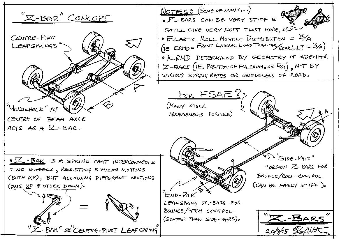
    Z, not sure if you noticed, but the 2012 UWA car is in fact your "Z-Bar Concept" drawing shown at top left. The differences are : "Centre-pivot Leaf Springs" replaced by the aero undertray acting as twin rocker-beams and also restraining the beam axles' rotation in the Y and Z axes. An ARB acts at the "centre-pivot" locations (as you mentioned in the "Suspension Design" thread). The "Monoshocks" are replaced with an innovative "W" spring which provides lat' and long' location in addition to springing. Dampers are located at each wheel.

    This is a very clever and innovative car with a very low suspension component count and one major suspension component doubling as an aero undertray. This design and future iterations are capable of great things.

+ Reply to Thread
Page 14 of 28 FirstFirst ... 4 12 13 14 15 16 24 ... LastLast

Posting Permissions

  • You may not post new threads
  • You may not post replies
  • You may not post attachments
  • You may not edit your posts