+ Reply to Thread
Page 9 of 28 FirstFirst ... 7 8 9 10 11 19 ... LastLast
Results 81 to 90 of 277

Thread: Beam Axles - Front, Rear or both.

  1. #81
    Senior Member
    Join Date
    Mar 2005
    Location
    Australia
    Posts
    1,690
    Harry,

    You ask, "So how a [centreline] Z-bar connecting [centres of] front and rear axles contributes to heave/pitch stiffness?"

    I think we have to start with a clearer description of what these "four-wheel-modes" mean. The following is not a rigorous definition (not enough space here) but hopefully it is of some help.
    ~~~~~o0o~~~~~~

    Firstly, think of the car's body fixed in space (as the reference frame) and the four wheelprints moving in a generally vertical direction wrt the body. Importantly, we are not concerned with the horizontal (x,y) or rotational (Wx, Wy, Wz) constraints of the wheels or their uprights, which are a function of the control arms (beams, wishbones, whatever). We are only concerned with the approximately vertical (z) motion of the wheelprints, which is the function of the spring-dampers.

    To specify the positions (heights) of the four wheelprints, wrt body, we need four numbers. The most obvious choice is LFz, RFz, LRz, and RRz (ie. the wheelprint "z" positions, or perhaps "altitudes" wrt car floorplane). A conventional "spring-at-each-corner" suspension follows this obvious approach and provides a single spring to control each of these numbers.

    Now, the fact is that we have four infinities of choices as to how we specify these "four degrees of freedom" (wheelprint heights). I won't go through all these choices , just the following "all-four-wheels" method.

    Here we specify our four numbers thus:
    1. Bounce mode, Bz = (LFz+RFz+LRz+RRz)/4. This is also called the "Heave" mode. As the equation suggests, this is the average height of all four wheels. We can picture this mode in motion as all four wheels moving up by an equal amount (or down for negative motion).
    2. Pitch mode, Pz = ((LFz+RFz)/2-(LRz+RRz)/2)/2. In words, half the difference between the average front-pair and rear-pair heights. We picture this as the two front wheels moving up, and two rear wheels moving down, an equal amount.
    3. Roll mode, Rz = ((LFz+LRz)/2-(RFz+RRz)/2)/2. Similar to Pitch mode, but turned 90 degrees.
    4. Twist mode, Tz = ((LFz+RRz)/2-(RFz+LRz)/2)/2 (aka "Warp" mode). This time, half the difference between the average heights of diagonal pairs.

    So, as an example consider a "single wheel bounce" of left-front wheel up four units (LFz = 4 inches, 4 cm, 4 whatever), and all other wheels at "zero".
    1. Bz = (4+0+0+0)/4 = 1 unit.
    2. Pz = ((4+0)/2-(0+0)/2)/2 =1 unit.
    3. Rz = (likewise) = 1 unit.
    4. Tz = (") = 1 unit.

    This is saying that a single wheel bounce of LF up 4 units (with all other wheels at zero) is equal to (Bounce = all wheels up 1 unit) + (Pitch = fronts up 1, and rears down 1) + (Roll = lefts up 1, and rights down 1) + (Twist = LF and RR up 1, and RF and LR down 1).

    I hope I'm not boring you, but a useful aspect of the above is that all the modes can be measured with simple linear dimensions (inches, metres), and angular measures for P, R, and T are not needed.
    ~~~~~o0o~~~~~

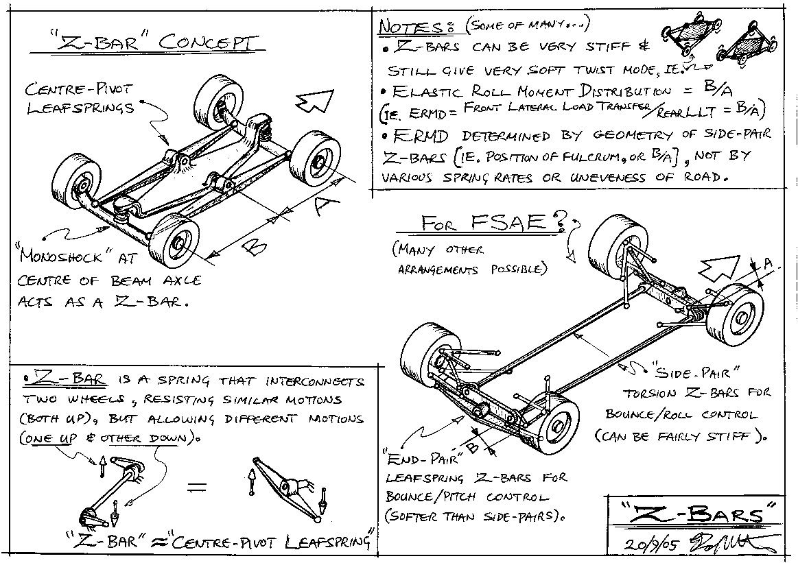
    Anyway, back to your original question. I will redisplay the Z-bar sketch below because 1) it's free, 2) it is too much of a hassle to display another sketch (the sketching is easy, but then scanners, file xfers, Picassa web wanks, ), and 3) hopefully it helps understanding.

    Looking at the top-left of the sketch, picture only one "centre-pivot-leafspring" (= a "Z-bar") on the car centreline. Picture the ends of this leafspring as ball-jointed to the centres of the F & R beams. So now the chassis sits ONLY on the centre-pivot of this single centreline leafspring.

    It should be apparent that NO Pitch, Roll, or Twist motions (as described above) can be transmitted FROM the wheelprints TO the chassis. So, the chassis responds ONLY to Bounce (=Heave) motions of the four wheelprints. So a centreline Z-bar is purely a Bounce mode spring. It does NOTHING MORE.

    The above can be seen by noting that the height of the BJ at the centre of each beam provides an average of the heights of the beam's two wheelprints. The height of the centre-pivot of the leafspring then provides an average of these two averages. Thus the whole linkage (2 beams + CPL) provides an average height of all four wheelprint heights, and nothing more.

    So, by INTERCONNECTING all four wheels, this linkage has SEPARATED the all-wheel Bounce mode from the other all-wheel modes (P, R, T). Similar (but a bit different ) linkages connecting all wheels can give separate, or "independent", control of each of the other modes.

    See SAE paper 2000-01-3572 "Balanced Suspension" , or US Patent No. 6,702,265 (lapsed), for neat ways of doing this.


    ~~~~~o0o~~~~~

    You ask, "As I see it we have two separate issues to be resolved:
    1st is axle location both longitudinal and lateral."


    The Mumford Link does lateral control of a beam. My comments in earlier posts about "springing the rockers" would add axle-bounce control (but not axle-roll control). Personally, I do not think the ML is necessary for FSAE (it has too many parts for my taste), but it would work.
    ~~~~~o0o~~~~~

    "2nd is control body movements....
    The real issue to me right now is which modes you want to control, why and how."


    As you say, with beam-axles it doesn't really matter how much the body moves, because the wheels always maintain the same camber. So Bounce, Pitch, and Roll can all be soft. For independent suspensions with little "camber recovery" (ie. long "virtual swing arms") it is beneficial to stiffen the Roll mode, but keep Bounce and Pitch soft (at least between limits, ie. bump stops). For sprung-aero cars the Bounce mode has to be stiff (to maintain constant ride height), but the Pitch mode can still be soft.

    VERY IMPORTANTLY, in all cases there are huge advantages in having a completely soft twist mode (again, between bump stops that limit the range of twist).

    It is truly astonishing that motorsports is the only sub-section of the "land vehicle" community that doesn't realise this! Even more incredible is that many of the people involved have been made aware of this, yet couldn't be bothered even thinking about it. Truly brain-dead!!! (Or just as likely, they have no need, or desire, to win!)
    ~~~~~o0o~~~~~

    "Actually the only movement I would like to limit somehow is single wheel bump. Any thoughts on this?"

    Why?

    The big advantage of a soft Twist mode is that it allows the car to easily drive over large single wheel bumps.

    Looking again at the example at the top of this post, if a car has rigid Bounce, Pitch, and Roll modes, and a completely soft Twist mode, then it can drive, even very slowly, over a 4" high single wheel bump with the car's CG only moving up 1", and the body only pitching 1" and rolling 1" (as defined earlier). (Picture top-left of Z-bar sketch with stiff leafs and coils, then look at top-right for the effect of a soft Twist mode.)

    Most importantly, the soft Twist mode means no changes to the vertical wheel loads over bumps (not considering inertia). That is why almost everyone else bar the motorpsorts community uses it. (See Appendix of above-referenced SAE paper for examples.)

    Z

  2. #82
    Z,

    First of all, thanks about all the info. Everything is put much much better than vehicle dynamics books I know and far easier to understand, so thank you (and I believe I speak for every member on the forum). I have already gone through the "balanced suspension" patent numerous times, and I have to admit it is more than interesting! (Actually I have a quite funny story behind that exact patent; have you ever heard about a Greek magazine called R&D? I bet you didn't, but they had a presentation on the "Zapletal suspension" back in 2006, so the first time I actually read it was when I was at highschool....)

    Anyway, the reason I thought a stiffer single wheel bump will be beneficial is the camber change at both wheels, as well as gyroscopic phenomena of the axle while during this...but I assume the latter can be cured with fairly soft "springing" and relatively high damping. Plus, as you said, "the soft Twist mode means no changes to the vertical wheel loads over bumps". A quick calculation says that I would have a total of 2.3deg camber change for 2" single wheel bump (improbable in a FSAE track), so I suppose I could trade that off for all the above gains.

  3. #83
    Senior Member
    Join Date
    Mar 2008
    Location
    Buffalo, NY USA
    Posts
    340
    Originally posted by Z:
    Here we specify our four numbers thus:
    1. Bounce mode,...
    2. Pitch mode,...
    3. Roll mode,...
    4. Twist mode,...(aka "Warp" mode).
    This is how the control system software for the Lotus Active Suspension was configured, starting in the early 1980's. By the time they got done, they built something over 80 prototype vehicles with variants of the system--from F1 cars to large single-unit trucks (for Volvo, among others). I drove a light tank fitted with a variant of the system that greatly reduced pitching, when compared to normal tracked vehicles.
    A search will turn up a number of pages with various descriptions. In typical racing (and "trade secret") style they did not do a lot of technical publishing. Most of the written documentation went to specific customers.

  4. #84
    Senior Member
    Join Date
    Mar 2005
    Location
    Australia
    Posts
    1,690
    Originally posted by mech5496:
    Anyway, the reason I thought a stiffer single wheel bump will be beneficial is the camber change at both wheels, as well as gyroscopic phenomena of the axle...
    ...
    A quick calculation says that I would have a total of 2.3deg camber change for 2" single wheel bump (improbable in a FSAE track)...
    Harry,

    It is worth considering how these "bumps" affect the suspension.
    ~~~o0o~~~

    First of all, bumps can come as "mountains", or as "molehills", ie. big or small.

    1. Let's say that "big" bumps have a smooth sinusoidal shape in horizontal directions (x and y), with a wavelength significantly longer than the car (so, say, 3++ metres). Sort of like longish waves, or "swells", on the ocean. Given the relatively low speeds of FSAE, a car driving over these "undulations" will not feel significant vertical accelerations of its wheelprints wrt body, so discussions about "unsprung weight" are frankly irrelevant. Likewise, gyroscopic forces are minimal, so changes in wheel inclination angle are not a problem.

    However, these undulations will twist the four wheelprints out of a flat plain, and thus very adversely affect the wheel loads of a stiff twist-mode suspension (ie. most racecars). So, a soft twist-mode is a big benefit here. Furthermore, in this case the best camber angles for the tyres is relative to the road surface as drawn as a straight line through laterally paired wheelprints. So the camber change of a beam-axle is just what you want.

    2. On the other hand, what about short wavelength bumps (say, <~1m wavelength)? I call these "corrugations". Now the accelerations are more severe, and, together with gyroscopic effects, suggest a suspension with lightweight wheel assemblies and NO camber change during the frequent single wheel bumps.

    Is the resulting "zero camber recovery" bad for cornering grip? Not really. The fact is that in this situation the wheels are rolling over ground that is constantly changing its relative "inclination" angle to the wheel. So for about half the time there is an effective positive camber angle, and the rest of the time there is an effective negative camber angle. If the bumps, or ruts, are short enough the wheel might have both positive and negative "camber" at the same time (ie. on either side)!

    In this case I think worrying about tenths of a degree of "camber recovery" is pointless. However, a soft twist-mode (as well as soft all-other modes) is beneficial because it gives more constant vertical wheel load, and thus better all round grip.
    ~~~o0o~~~

    To sum up:

    1. For smooth "undulating" roads, like circuit racing and FSAE, the car benefits from a soft twist-mode, and wheels that are kept at a constant camber angle relative to a line drawn through lateral pairs of wheelprints. So, for example, use beam-axles, or lateral swing arms with a lateral Z-bar that minimizes "axle-bounce", but allows "axle-roll".

    2. For harsh "corrugated" roads, like rallying and off-road racing, the car benefits from a soft twist-mode, and wheels that are kept at a constant camber angle relative to the body. So, for example, use leading and trailing arms, or, if you must use lateral wishbones, make them long, equal length, parallel, and horizontal at normal ride height.

    Z

    (Edit: It is instructive to draw a "map" of the type of bumps that ground vehicles drive over. On the the horizontal axis plot "Frequency" (Hz) as a log scale. On the vertical axis plot "Amplitude" (say, in metres) again as a log scale. Now, assuming sinusoidal bumps, the maximum vertical velocities and accelerations of the wheelprints are shown as two series of diagonal lines on the map (different slopes for V and A). FSAE is at the bottom-left of this map (along with forklifts, etc.), while desert racers are at the top-right.)

  5. #85
    Z,

    As much as I love the idea of a simple go-kart type FSAE car, I look at the sketches and ideas in this thread and wonder where the simplicity is!

    Teams aren't just using wishbones and push/pullrods because that's what "real" single seaters use; they use them because they're easy to make. The parts are almost all built from simple materials (rods, tubes, plates etc) that are all small and manageable to fabricate.

    Sure, there can be "interesting" handling characteristics if the geometry is poor, but the teams who only care about getting a car going can just weld up a few tubes (with the required rod ends in bending) and get out on track. Teams who know what they're doing can spend a while analysing the kinematics for decent geometry, with a large amount of existing resources to guide them.

    The ideas here require large parts and assemblies that would need to be fabricated, either by machining (expensive for large parts) or casting (expensive for anything). Not only are the systems you're advocating likely to cost more to produce than a double-wishbone setup (which puts off the poor teams), they'll also put off the lazy teams as they'll have little to guide them, meaning they have to design the whole thing themselves!

    A go-kart would be fantastic, but unfortunately we're required to have suspension. In trying to accommodate the requirements while avoiding double-wishbones in the name of "simplicity" I think you've done the opposite.

  6. #86
    Senior Member
    Join Date
    Mar 2005
    Location
    Australia
    Posts
    1,690
    Originally posted by Tickers:
    ... I look at the sketches and ideas in this thread and wonder where the simplicity is!
    Tickers,

    Groan!!! I have heard this line so many times before...

    People do things in ridiculously complicated ways, and then say "Oh, it's not difficult at all!"

    Why???

    Because that's the way they have always done it!
    ~~~o0o~~~

    You say, "Teams [use wishbones] because they're easy to make."

    And, The ideas here require large parts and assemblies that would need to be fabricated, either by machining (expensive for large parts) or casting (expensive for anything)....

    I suspect that the above is just a leg-pull, but if not, then it is pure crap!

    I have been through the "easy to make" process of wishbones, and while I agree that it is a mind-numbingly boring and brainless job, that fact is that making all those little gubbins, fishmouths, gussets, etc., MULTIPLIED BY EIGHT, takes a long time.

    The two beams I drew would be fabricated from a few lengths of tube and some sheet-steel gussets (no "machining large parts", or "casting" - where did that crap come from!!!). From past experience I reckon it would take about half the time of a full wishbone setup.

    But the even bigger gain comes from the simpler chassis with its much smaller number of hardpoints. Only four of these hardpoints need to be accurately positioned, and they are all on the centreline of the chassis. So much easier than when hardpoints are scattered all over the place.
    ~~~o0o~~~

    It never ceases to amaze me how fearful Homo Sapiens are of change. Even the young ones!

    Any pissweak excuse to avoid change will do, "... have to design the whole thing themselves!".

    Any FSAEers with testicles out there?????

    Z

  7. #87
    Z, you have to admit there are terribly complicated ways to build a beam axle... Like the concept our team evaluates, which you might all see as long as we finish the manufacturing of our current car. Tickers, simple beams can be built very very cheaply and easily. Polished-up concepts to shave off some unsprung are a bit more complicated, but even if you say that it has the same complexity with a double wishbone setup, I'm pretty convinced there ARE performance gains in beam setups. You just have to think it as the whole system, not just the suspension... Right now you are staring at the tree, while missing the woods behind it....

  8. #88
    Originally posted by Z:
    <BLOCKQUOTE class="ip-ubbcode-quote"><div class="ip-ubbcode-quote-title">quote:</div><div class="ip-ubbcode-quote-content">Originally posted by Tickers:
    ... I look at the sketches and ideas in this thread and wonder where the simplicity is!
    Tickers,

    Groan!!! I have heard this line so many times before...

    People do things in ridiculously complicated ways, and then say "Oh, it's not difficult at all!"

    Why???

    Because that's the way they have always done it!
    ~~~o0o~~~

    You say, "Teams [use wishbones] because they're easy to make."

    And, The ideas here require large parts and assemblies that would need to be fabricated, either by machining (expensive for large parts) or casting (expensive for anything)....

    I suspect that the above is just a leg-pull, but if not, then it is pure crap!

    I have been through the "easy to make" process of wishbones, and while I agree that it is a mind-numbingly boring and brainless job, that fact is that making all those little gubbins, fishmouths, gussets, etc., MULTIPLIED BY EIGHT, takes a long time.

    The two beams I drew would be fabricated from a few lengths of tube and some sheet-steel gussets (no "machining large parts", or "casting" - where did that crap come from!!!). From past experience I reckon it would take about half the time of a full wishbone setup.

    But the even bigger gain comes from the simpler chassis with its much smaller number of hardpoints. Only four of these hardpoints need to be accurately positioned, and they are all on the centreline of the chassis. So much easier than when hardpoints are scattered all over the place.
    ~~~o0o~~~

    It never ceases to amaze me how fearful Homo Sapiens are of change. Even the young ones!

    Any pissweak excuse to avoid change will do, "... have to design the whole thing themselves!".

    Any FSAEers with testicles out there?????

    Z </div></BLOCKQUOTE>

    Z, there is a limit to the steps in thickness of availible material for these giant leaf springs with big center pivots. I can cheaply buy coil springs in 5 lbf/in increments to tune my suspension, and a few click on the damper or a spin on my 5" long ARB blades. How does one tune this great big deal? A truckbed of leaves of spring steel?

    Also, twist modes aside, there's a lot to be said about camber thrust and adjusting your suspension to give you the camber you need under roll to improve grip. Sidewalls are compliant, and often not to our advantage.

    That said, this IS an interesting concept. They said rear steer could not work on the Thrust SCC, but some guy made it happen. Are you willing to help make it happen for a team, or just for a demonstration?

  9. #89
    Senior Member
    Join Date
    Mar 2005
    Location
    Australia
    Posts
    1,690
    (More groaning... "like trying to put brains into statues....", grooooaaan....)

    whiltebeitel,

    You say, "there is a limit to the steps in thickness of availible material for these giant leaf springs..."

    At the top-left of the sketch it says "Z-Bar Concept". I drew the "centre-pivot leafsprings" for those "imaginatively challenged" students who can't figure out how a torsional Z-bar works. The lateral CPLs shown at bottom-right are the sort of thing that an apprentice blacksmith could make without a second thought. But a bit too much for you??? (Mumble, mumble, "education system, grrrr...")
    ~~~o0o~~~

    "How does one tune this great big deal?"

    Top-right! ERMD (=LLTD) = B/A.

    (Key point: By geometry NOT spring rate!)
    ~~~o0o~~~

    Are you willing to help make it happen for a team, or just for a demonstration?"

    Read the Appendix of the SAE paper referenced above (just above Z-bar Sketch this page). As explained there, twist-soft suspensions are by far the most common for real working vehicles. Motorsports is in a tiny minority that hasn't figured it out yet. (Braindead!!!!)

    Z

  10. #90
    Originally posted by Z:
    Read the Appendix of the SAE paper referenced above (just above Z-bar Sketch this page). As explained there, twist-soft suspensions are by far the most common for real working vehicles. Motorsports is in a tiny minority that hasn't figured it out yet. (Braindead!!!!)

    Z
    Any relation the the author?

    It's a wonder more of your ideas have not caught on, with such a flowery personality and charm.

+ Reply to Thread
Page 9 of 28 FirstFirst ... 7 8 9 10 11 19 ... LastLast

Posting Permissions

  • You may not post new threads
  • You may not post replies
  • You may not post attachments
  • You may not edit your posts