+ Reply to Thread
Page 2 of 6 FirstFirst 1 2 3 4 ... LastLast
Results 11 to 20 of 57

Thread: Upright Mass Comparison

  1. #11


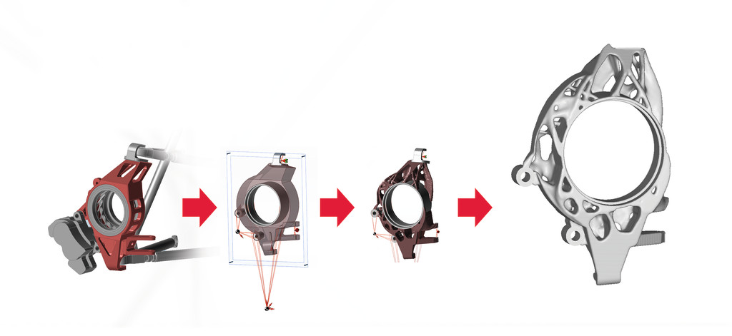
    This one: 440g full blown topology optimization with camber and toe stiffness as design targets, then a 3d-printed mold pattern and then cast from aluminium. Not an actual part for a car, only done for demo purposes of a nice simulation driven product development process ;-)
    Lutz Dobrowohl
    2008-2011
    Raceyard Kiel

    Now: Scruitineer, Design Judge, application engineer @Altair engineering

    Whatever you do, do it hard!

  2. #12
    MCoach,
    I don't know if you can post some photos of your 2015 uprights.
    I'am really interested to see your sheet uprights design.
    Thank you in advance.

  3. #13
    Quote Originally Posted by Ahmad Rezq View Post
    MCoach,
    I don't know if you can post some photos of your 2015 uprights.
    I'am really interested to see your sheet uprights design.
    Thank you in advance.

    I have some of the 2014 design for sure. Not sure on 2015 model. They were a pain to weld, I can say that at least.
    Kettering University Vehicle Dynamics
    Formula SAE 2010 - 2015
    Clean Snowmobile Powertrain 2012 - 2015

    Boogityland 2015 - Present

  4. #14
    Senior Member
    Join Date
    Mar 2005
    Location
    Australia
    Posts
    1,690
    Quote Originally Posted by JT A. View Post
    One thing I've never seen is someone put a specific value on how stiff they need to be for camber & toe control, with solid reasoning behind it. Especially toe compliance.
    JT A.,

    I posted such numbers with reasoning back in 2005. In the last ~4 years I have linked back to those posts several times, and added more numbers and reasoning. Over the years, many other people have done same. Bill has just added yet another such post. There are even some papers/theses floating around the web, which give good numbers and reasoning on the similar issue of "How torsionally stiff does a FS/FSAE chassis need to be?".

    In all cases, the answer is that below a certain level of stiffness the performance is adversely affected (by a quantifiable amount). Slightly higher levels are "good enough" (quantifiably!). And really high stiffnesses are a tiny bit better again, but cost a great deal more (again, quantifiably...).

    So, are all these numbers and reasoning making any difference?

    Judging by the many design cock-ups I keep seeing, the answer is mostly NO! Why?

    It seems to boil down to the current generation of students' lifetime of indoctrination (since first kindy classes) that:
    "THERE ARE NO RIGHT OR WRONG ANSWERS! Each and every person's opinion is equally valid. And regardless of how catastrophically your uprights fail, you all deserve a gold-star!" <- And the dim-witted hordes believe it!

    I am not exaggerating. It is becoming quite painful seeing and hearing it over and over again...
    ~o0o~

    Matt,

    Given you have failed in your attempt to post a pic here (I keep getting "Server Not Found"), I am dubious of your FEA optimisery skills. Just ~300 grams???

    Can you try to post some pics again?
    ~o0o~

    MCoach,

    Sheet-steel ~0.6 mm thick (0.025") is easiest spot-welded, or else brazed, or else bend the two mating edges into "lips" which are pressed together, then run a fine TIG spark directly over the lips to melt them together. This last technique, or similar with brazing, can be used "sheet to sheet", and also at the "sheet to bearing-housing" joints.

    Knowledge transfer of such techniques can be a huge asset to a Team.

    Z
    Last edited by Z; 04-17-2016 at 11:00 PM.

  5. #15
    Just take the http:// off the front of the link

    imgur.com/a/OCsKX

    I would be surprised if they were 350g. The toe link extensions look quite delicate too.
    Adam Flower
    Head Engineer, 2015, 2016
    Ergonomics Team Leader, 2014
    UTAS Motorsport
    Tasmania

  6. #16
    Quote Originally Posted by Z View Post

    Sheet-steel ~0.6 mm thick (0.025") is easiest spot-welded, or else brazed, or else bend the two mating edges into "lips" which are pressed together, then run a fine TIG spark directly over the lips to melt them together. This last technique, or similar with brazing, can be used "sheet to sheet", and also at the "sheet to bearing-housing" joints.

    Knowledge transfer of such techniques can be a huge asset to a Team.

    Z

    0.025" steel can be easily welded"

    I think it would also be equivalent to say that transferring championship-winning driving skills would also be great skills to transfer onto the team. Or teaching one how to appreciate fine art. Some things just require some developed technical skills. It's hard enough teaching people to weld for the first year or two.
    Spot welding will hold them together to look pretty, but you'll need some more structural welds there to hold them together on the car.


    I found a picture of the front upright, but I'm having some technical difficulties uploading it.
    Kettering University Vehicle Dynamics
    Formula SAE 2010 - 2015
    Clean Snowmobile Powertrain 2012 - 2015

    Boogityland 2015 - Present

  7. #17
    Last edited by Ahmad Rezq; 04-18-2016 at 03:28 PM.

  8. #18
    Senior Member
    Join Date
    Mar 2005
    Location
    Australia
    Posts
    1,690
    Quote Originally Posted by MCoach View Post
    Spot welding will hold them together to look pretty, but you'll need some more structural welds there to hold them together on the car.
    MCoach,

    Ask google to show you images of "spot welding". Look at most any modern car...

    The education system is truly dead...

    Z

  9. #19
    Senior Member
    Join Date
    Mar 2005
    Location
    Australia
    Posts
    1,690
    Matt,

    Not only have you failed to post a pic of your uprights, but you have failed on the strength and stiffness targets, and you have even failed to get the CAD system to calculate the right mass!

    Put on the dunce's cap and go sit in the corner.

    Z

  10. #20
    Senior Member
    Join Date
    Nov 2010
    Location
    NSW, Australia
    Posts
    352
    Matt,

    If you ever come back, try to filter the bile from the useful information in Z's responses. Unfortunately he's about the only person to have been born with the entire world of knowledge already available to him, and likes to remind people of such. Thus, anybody trying to learn is a dunce and an example of a failed education system.

    That being said, I suggest you have a good look at other upright designs (go visit some nearby teams). If nothing else, this should give you an idea of mass and of how 'strong' an upright should look, as well as giving you an idea on machinability. Hopefully, one of the nearby teams will have sheet steel examples!
    Jay

    UoW FSAE '07-'09

+ Reply to Thread
Page 2 of 6 FirstFirst 1 2 3 4 ... LastLast

Posting Permissions

  • You may not post new threads
  • You may not post replies
  • You may not post attachments
  • You may not edit your posts