+ Reply to Thread
Page 6 of 8 FirstFirst ... 4 5 6 7 8 LastLast
Results 51 to 60 of 77

Thread: Hubs with built-in tripod joint

  1. #51
    Josh,
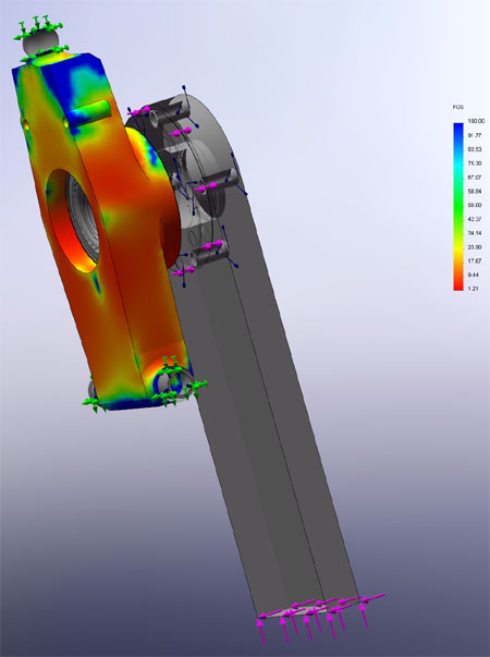
    I think the loads will be applied to half of circumference in case of (Fx and Fz).
    Fy will be transmitted from the bearing to the bearing shoulder on the upright

    http://help.solidworks.com/2015/engl...stribution.htm

    Someone correct me if I'am wrong.

  2. #52
    Josh, since you have the hub and bearing models, why not include them in your FEA? You can set them as hiddens (I think that's the word? Been a while since I've used SW FEA) so stress analysis isn't done on them, but they can be used to transmit loadings.

    I'll leave this here for you to look at:

  3. #53
    Senior Member
    Join Date
    Oct 2007
    Location
    Bolton, CT
    Posts
    144
    Your analysis is done in Solidworks, right? All of my terminology is for ANSYS and I personally recommend using it, or at least something a little more powerful than Solidworks FEA, just for the extra options. I haven't used Solidworks in a while (since the COSMOS days) so I'm not terribly useful on that front.

    My advice is to run analysis as fully assembled as you can. By this, I mean that I would put the upper and lower ball joint brackets into the model. You can then apply constraints to the bracket/upright interfaces to force them together just as the bolts would or alternatively you can make sure they form compression-only supports which are aligned by the bolt holes (sorry for the poor explanation here). Including the ball joint brackets in your model allows you to better constrain it since you now do not have to assume each is fixed. You can fix the ball joint bolt holes as compression-only supports (just as bolts are since they are not glued to the interface) so they do not limit rotation. You want the tie rod attachment point to limit rotation just as in the real car by making it a compression-only support. You now need a constraint to stop upward movement in the z-direction just like the spring/damper unit does. To do this, put a compression-only support or fixed constraint on the ball joint mount face which opposes upward motion (ie: the one that holds the ball joint with the a-arm that has the damper or push/pull rod mount).

    If you can get all of that set up, you can move onto loads.

    For loads, calculate (or estimate) the loads you will have at the tire/ground interface. You are going to have an Fx (longitudinal acceleration), Fy (lateral acceleration), and Fz (vertical/normal force). You now want move this force onto the central axis of the bearing since this is where it is going to be reacted. Use a bearing load to apply the force components to the bearing surfaces. Bearing loads distribute radial force components onto only the compressive side using projected area and distribute axial components uniformly like an ideal bearing would theoretically do. Applying the force this way will allow you to see the bearing surface deformations as well as the angular bearing axis misalignment, both which are important when looking at bearing life.

    You can load up the brake bolts in a similar way as they will react the same. Go through the same process and assign each bolt a specific bearing load based on the braking force at the pad and moment equations to transform it onto the attachment bolt axis.

    Once you get a model running, you’re going to want to do a mesh refinement study to be sure your results are grid independent. To do this, refine you mesh more from the base mesh and run the same exact analysis again. If they results are vastly different, your solution was not grid independent and you should refine the mesh until the solution does not change. Note that grid independence does not mean the solution is correct, just that the math was solved correctly. Since linear FEA is pretty simple compared to other numerical analyses, when you find your solution is grid independent you can usually assume it is also physically correct (assuming your boundary conditions are correct).

    To learn more about what I wrote above, look up the “ANSYS Static Structural Analysis (Chapter Four)” on Google and download the first link. Note, it is not current but is easy to find and has some good pictures and descriptions.

    Sorry for the long post, I hope some of that makes sense. I was trying to write fast so I cheated and didn’t draw pictures, but if you’re unsure just post up another picture of your FEA with constraints and the forum can critique. Also be sure to put up your assumed loads.

    ---Edit #2---
    Tromoly's way of doing it is pretty good too. He applies the same BC I am suggesting, but does it in a more physical way. There are a few extra constraints.
    Last edited by jd74914; 11-06-2015 at 05:06 PM.
    Jim
    "Old guy #1" at UCONN Racing

  4. #54
    There are a lot of wrong ways to do analysis with the bearing races and the interface to the hub. EVERY method that has been mentioned so far is ONLY useful for relative comparisons between your models, none will give you realistic numeric results for deflection or stress. Break out NASTRAN and MMPDS, and get comfortable with contact modeling and FORCE1 cards if you want to really understand what's going on. Then again this is what safety factors are for...

    Ahmed: a bit warmer, but those distributions assume a rigid load applicator
    Tromoly: your upright is overconstrained.
    Jim: as far as I am aware, ANSYS bearing loads also assume a rigid applicator. Of course if you decide that's a reasonable assumption, then that's fine. Also grid dependence is usually a product of using constant strain (linear displacement) elements. Try using quadratic element formulations and solve your models faster and more accurately.

    Z's method is closest, but doesn't solve the problem that you still need to constrain something! Any RIGID BODY in 3-space needs 6 constraints, however the upright is not a rigid body, upright strains are what we're interested in anyway! A FBD around the upright ALONE has the forces from links to chassis PLUS forces at the bearing races! Can't ignore those.

    Relatively realistic modeling process:
    - Solid meshed upright. Prefer hex-mesh, tets are constaint strain elements and thus require much finer mesh to get good results.
    - rigid links (use RBARS) with nodes at actual joint locations. Can fix the chassis nodes, or better yet integrate with your chassis CBEAM model! but make it useful before complicated
    - RBE2 spiders between BJ lug hole edges and RBAR outboard nodes. This is unrealistic, but you won't get the mesh fine enough to learn anything that you can't learn by doing bearing stress hand-calcs
    - Modeled bearing race and hub, likely with plate elements to make it easier and faster
    - Linear contact between bearing race and upright surfaces using gap elements
    - Apply tire forces and moments via rbe3 to hub rim interface. Extra points for using your rim plate model and maybe even a tire plate model (!!!)

    I'm not saying everyone _should_ do this, but if you're _not_ doing this or similar than your numbers are suspect. Maybe not trash, but if you strain gage your uprights in high-gradient areas they won't agree with the model.

    Tying into the thread topic a bit more. Sheet welded plate uprights are SIMPLE to model because you can just use CQUAD4s. Will solve literally orders of magnitude faster than a solid model. And you can learn more because "geometry" is easy to change by just changing the property cards.
    Why has my team never down sheet welded uprights? Because we are TERRIBLE at welding. In fact before January 2015 we were not allowed to weld in our school! On the other hand, we are damn good machinists if I may say so myself.


    Takeaways:
    - Solidworks FEA is USEFUL but it sucks for getting real numbers
    - Make it useful before you make it complicated
    - Garbage in, garbage out
    Last edited by Adam Farabaugh; 11-06-2015 at 05:03 PM.
    Penn Electric Racing

  5. #55
    Of course, since you're a first year team, the past to best success probably involves not doing any FEA at all and just building the thing. I'm not joking. You'd rather have a floppy car that runs rather than a rigid car that doesn't.
    Penn Electric Racing

  6. #56
    Senior Member
    Join Date
    Oct 2007
    Location
    Bolton, CT
    Posts
    144
    Quote Originally Posted by Adam Farabaugh View Post
    There are a lot of wrong ways to do analysis with the bearing races and the interface to the hub. EVERY method that has been mentioned so far is ONLY useful for relative comparisons between your models, none will give you realistic numeric results for deflection or stress. Break out NASTRAN and MMPDS, and get comfortable with contact modeling and FORCE1 cards if you want to really understand what's going on. Then again this is what safety factors are for...

    Jim: as far as I am aware, ANSYS bearing loads also assume a rigid applicator. Of course if you decide that's a reasonable assumption, then that's fine. Also grid dependence is usually a product of using constant strain (linear displacement) elements. Try using quadratic element formulations and solve your models faster and more accurately.
    Yes, you're definitely right; all of this analysis is only useful for making model change comparisons and is not rigorously correct. IMHO to the rigid bearing assumption is the weakest point in the model since this is likely the portion of the with biggest deviation from real world.

    That said, I've always thought that was a reasonable assumption for comparison purposes, albeit not totally correct. A more rigorous model certainly has a bearing in there (and really a hub, bearing...) because it does have finite deflection.

    Agree on the quad elements too...much better. I'm a CFD guy and I always recommend people stay away from Tets; Quads or Polyhedral (for highly skewed shapes) only. On simple models it is always nice to see grid independence. Like you said, with good choice in element type this might not be a useful study, but until you have a feeling for how small your elements need to be etc., I think seeing the differences between meshes is valuable.
    Jim
    "Old guy #1" at UCONN Racing

  7. #57
    Senior Member
    Join Date
    Mar 2005
    Location
    Australia
    Posts
    1,690
    Adam,

    Z's method is closest, but doesn't solve the problem that you still need to constrain something! Any RIGID BODY in 3-space needs 6 constraints, however the upright is not a rigid body, upright strains are what we're interested in anyway! A FBD around the upright ALONE has the forces from links to chassis PLUS forces at the bearing races! Can't ignore those.
    Read my post again! I gave essentially the same method as you and Jim, which is to use the six suspension links as the "constraints", and then load the upright at the caliper-mounts and bearing-surfaces.

    I also clearly indicated where the "forces at the bearing races!" should go. Namely (quote from my post ->), "3. Distributed down-right forces on both bearing-mounting surfaces (distributed from ~3 to ~7 o'clock, but mostly around ~5 o'clock).", for the particular braking-only case I was describing.

    I stand by my view that,
    * shortly after students were given calculators ... they could no longer do simple sums,
    * and when they got word-processors ... they could no longer spell, or write, OR EVEN READ (!),
    * and when they got CAD/FEA/CFD+++ ... they could no longer solve the simplest engineering problems, such as doing simple FBDs!

    Grooooaaannn..., mummmble...
    ~~~o0o~~~

    Josh,

    I await a colourful deformation diagram of your first upright under the load conditions suggested in my last post.

    Z

  8. #58
    Quote Originally Posted by Adam Farabaugh View Post
    Tromoly: your upright is overconstrained.
    It's not my picture/upright, I was using it to show the upright/bearing/hub assembly with a piece standing in as the tire.

    But just for discussion, would you be talking about the toe link having too many constraints on it?

  9. #59
    Senior Member
    Join Date
    Mar 2005
    Location
    Australia
    Posts
    1,690
    Tromoly,

    "...would you be talking about the toe link having too many constraints on it?

    Hard to see clearly, but it seems all three corners of the upright in your image (ie. 1 x top-BJ and 2 x bottom-BJs) are constrained in ALL THREE X, Y, and Z directions.

    A typical toe-link can only "constrain" its upright-BJ in the car-coordinate ~Y-direction (ie. in direction of toe-link tube). Any X or Z constraints at the toe-link-BJ will artificially "stiffen-up" the upright.

    Result = worthless FEA.

    Z
    Last edited by Z; 11-06-2015 at 09:39 PM.

  10. #60
    Quote Originally Posted by Z View Post
    Result = worthless FEA.
    I went back and looked at the suspension arm the upright attaches to, and actually for that given application it's not worthless.


    The arm is on an Ariel Atom, which for some reason has the toe link welded to the suspension arm, so it actually is constrained properly for that particular vehicle. The toe link design is still garbage (way to go Ariel!), though.

+ Reply to Thread
Page 6 of 8 FirstFirst ... 4 5 6 7 8 LastLast

Posting Permissions

  • You may not post new threads
  • You may not post replies
  • You may not post attachments
  • You may not edit your posts