+ Reply to Thread
Page 7 of 8 FirstFirst ... 5 6 7 8 LastLast
Results 61 to 70 of 77

Thread: Hubs with built-in tripod joint

  1. #61
    Senior Member
    Join Date
    Oct 2008
    Location
    Raleigh, NC
    Posts
    232
    The Ariel Atom has some odd design choices*.
    The fellow at DPcars.net documented his efforts to deal with them here: http://www.dpcars.net/atom/
    That said it does look great!

    -William

    *example: regressive shock geometry, the "hole" in the bottom of the chassis where he put braces

  2. #62
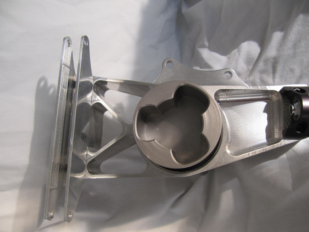
    Before I do FEA, let's get the preliminary design correct, and handle wall thicknesses and webbing later.

    Does this look like what people are suggesting I do to increase my toe-base? With 10-inch wheels, it seems to be one of only two options, the second being a side-mounted toe link, rather than beside one of the two BJ. I like this solution the best because it is easier to limit bump-steer.

    I only spent 5 minutes on this design so I can come back and iterate, or leave, the design.

    Let me know what you think,
    Josh

    Rear Clevis Top.jpgRear Clevis Angle.jpgRear Clevis Angle 2.jpg
    Joshua Byington

    Boston University Racing

  3. #63
    Josh,
    I don't know at which point you are in now regarding (Billet upright vs sheet metal upright).
    But
    How about designing a bent style bracket (laser cut + bending) to be mounted on the upright.
    One bracket for both control arm + tie rod joints.
    We manufactured 10 brackets with almost 10 EGP ~ $1.25 per bracket (Material which is 4mm St.50+Laser cutting+bending process) and save some time in manufacturing.
    Last edited by Ahmad Rezq; 11-10-2015 at 01:05 AM.

  4. #64
    Hey Ahmad. That sounds like good way to make these. Should I use this design, I will likely waterjet steel and bend the shape, adding a flat plate at the right side. The curved surface is more difficult to support..

    Josh
    Joshua Byington

    Boston University Racing

  5. #65
    While that's common in industry (have a look at knuckles on a lot of cars and you see them dodging the rim/tire) it looks heavy and or floppy. Try this:

    http://imgur.com/TgUa0lw
    Penn Electric Racing

  6. #66
    Trying to pull off that kind of a shim is similar to teams doing swan neck wing supports. Have fun FEAing to make it safe/stiff !

    Also, would you prefer some bump steer over compliance steer ?
    Last edited by P^squared; 11-09-2015 at 06:39 PM.

  7. #67
    Quote Originally Posted by Joshkb View Post
    Before I do FEA, let's get the preliminary design correct, and handle wall thicknesses and webbing later.

    Does this look like what people are suggesting I do to increase my toe-base? With 10-inch wheels, it seems to be one of only two options, the second being a side-mounted toe link, rather than beside one of the two BJ. I like this solution the best because it is easier to limit bump-steer.

    I only spent 5 minutes on this design so I can come back and iterate, or leave, the design.
    Probably way too late at this point, but you can sacrifice a little camber compliance of the upright by shortening the height of the UBJ and toe pick up to be able to spread them out in the wheel further. That would stiffen up your toe compliance. You know, if you really need it. Certified 5 minute analysis.
    Kettering University Vehicle Dynamics
    Formula SAE 2010 - 2015
    Clean Snowmobile Powertrain 2012 - 2015

    Boogityland 2015 - Present

  8. #68
    Senior Member
    Join Date
    Mar 2005
    Location
    Australia
    Posts
    1,690
    Google "images of racecar suspension uprights" and amazing how many pics of FSAE stuff you get. This one from SJSU (San Jose State?).


    As Adam and MCoach suggested, by moving the "channel-section" (at left of image) closer to wheel centre (towards right) by ~1/2" allows you to increase toe-base by ~1" (edit: while keeping everything INSIDE the wheel shell).

    The channel-section, which is bolted to the upright, but bolts not seen in image, can be machined-aluminium, or extruded-aluminium C-section, or folded-steel as suggested by Ahmad, or even a steel RHS ~20 mm x 65 mm (x 2-3mm thk) which is cut lengthwise to make two channels 20 mm x 30 mm. Extra speed-holes optional...

    Z
    Last edited by Z; 11-09-2015 at 07:39 PM.

  9. #69
    Ya, I would really like to keep the knuckles inside my wheel so I don't have to extend them so far, which I really don't think is a good idea. The design posted here has a toe-base of 120mm (4.7").

    Josh

    Internal Clevis, Rev2.jpg
    Joshua Byington

    Boston University Racing

  10. #70
    Ah, didn't even see that Adam said the same thing. Nice.
    I think our rear has a toe base somewhere on the order of 5 - 6", also running 10" wheels.

    If you're worried about stiffness and reacting forces from the contact patch, take a look at the Calspan data for the tires you are using. If you check out the pneumatic trail, that should give you an idea of where to point your caster trail. If they coincide there is essentially no distance for a moment to be formed. Work smarter not harder. Of course the trail and contact patch center will move around, but you'll have some general location to aim for.
    Kettering University Vehicle Dynamics
    Formula SAE 2010 - 2015
    Clean Snowmobile Powertrain 2012 - 2015

    Boogityland 2015 - Present

+ Reply to Thread
Page 7 of 8 FirstFirst ... 5 6 7 8 LastLast

Posting Permissions

  • You may not post new threads
  • You may not post replies
  • You may not post attachments
  • You may not edit your posts