+ Reply to Thread
Page 3 of 18 FirstFirst 1 2 3 4 5 13 ... LastLast
Results 21 to 30 of 180

Thread: Vehicle Dynamics starting points and design process

  1. #21
    Quote Originally Posted by ChristianChalliner View Post
    http://i1296.photobucket.com/albums/...ps36ee34ae.png

    Advantages - CofG is low down, could only be lower with a pull rod under the floor (The reason I've not done this is because I'm pretty sure the valving in the damper will be backwards (as in compression is a pull, rebound is a push) and I don't know if we will be able to get the shocks re-valved (yet!)). Other advantages are that the motion ratio can be altered and digressive, linear or rising rate springing can be achieved with the rocker design.

    Disadvantages - As you can see, it makes life difficult with the footwell template, again more complexity, more nodes to reinforce, larger forces through the 'pull rod' due to the angle, etc. Probably more!
    Think 3D and install the shocks longitudinally, directed to the back, with the pullrod design? CoG low down and nearer to the middle of the vehicle, and shocks not interfering with the template... Just a thought.

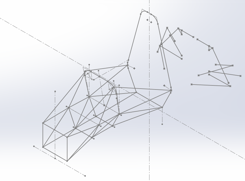
    I know, Z will hate me for the CF A-arms, pullrod, monocoque and unnecessary complexity visible in this picture

    Jan Dressler
    07 - 09 High Speed Karlsruhe / UAS Karlsruhe: Engine & Drivetrain Team
    09 - 10 High Speed Karlsruhe / UAS Karlsruhe: Engine & Drivetrain Team Leader
    10 - 13 High Speed Karlsruhe / UAS Karlsruhe: hanging around & annoying the team with random FSAE wisdom
    13 - ?? Gätmo Motorsport

  2. #22
    Senior Member
    Join Date
    Mar 2005
    Location
    Australia
    Posts
    1,690
    Quote Originally Posted by ChristianChalliner View Post
    Your point of spending as much time testing as designing/building makes sense, I actually put forward some of the points raised to a few team members today and what I remember most was the chassis guys comment "Yeah I get that but I want to design it right to start with" so you can see the mentality we've had instilled in us here.
    Christian,

    Ooooo..... I think the above could be your biggest problem...

    As so many here have said, it is of utmost importance that you get a driveable car sooner rather than later.

    So, what to do?

    I am the last person to advise you on this (my methods are much too old-school!). Perhaps try to convince as many other team members of the importance of an early build (= everlasting glory!), and then use "democratic pressure" to, err..., "encourage" the slackers to keep up. There might come a time when other Team members will have to step in and "help" finish off a particular part of the car. Basically, tell any "weakest links" that the rest of the Team wants to enjoy some success.

    Does anyone else have some more new-age-ish acceptable advice?
    ~~~o0o~~~

    Front-View Suspension Sketches.
    ========================
    The Direct-Acting-Spring-Dampers are more than good enough. (Edit: And you can lower the CG by having the top-SD-mount quite a bit lower, perhaps at top-SIS height, so about 300 mm above ground...)

    In FS conditions there is NOTHING to be gained from rising/linear/falling rates via rockers. Rising rates can be had through bump-stops (the best way, because most adjustable). Falling rates through droop-limiting (extensively covered by myself back in 2005, though very few people here get this yet). See the Cincinatti car at one of the 2014 US comps for a really good example of how to quickly adjust spring rates. (<- I can find these various links if you want.)

    Your sketched wishbones suggest a FVSA Length of about 3/4 track-width. Going for the Lancaster-Link style suspension, with FVSAL = 1/2 track, has a lot of practical advantages. Perhaps most important is that it greatly reduces compliance issues, and also greatly simplifies the frame. (I recall discussing this before, but I lost all my PMs in the Great-Forum-Shift of 2013...)

    Of course, using Beam-Axles all around ELIMINATES ALL CAMBER-CHANGE COMPROMISES during Heave, Pitch, or Roll. The camber NEVER changes! (Well, except for tyre squash, and steering-geometry.) But Suspension Kinematics are not very important in FS/FSAE. The LL style suspension has good enough Kinematics, and is very simple structurally. (BTW, the frame bottom rails can be horizontal and just above ground (ie. flat floor), with the LLs above them as they converge to the car centreline.)
    ~~~o0o~~~

    "General Arrangement" Sketches.
    ========================
    These are most important at this stage. So some "three-view" sketches (ie. Plan-View, Side-View, and End-View) of the whole car, showing bold outlines of driver, engine, and wheels, and lighter outlines of frame, suspension, and steering. There is really not much point going into small details until you have a good idea of this "big-picture".

    A key design point here, that you will NOT get from any of the Simulations mentioned so far, is that you should try to squash the engine as far rearwards as possible. This means minimising the distance between engine output sprocket and diff, and possibly mounting the diff BEHIND the rear-axle line (eg. about 5 - 10 cm). This minimum engine-diff distance can be achieved with a gear-train (difficult, and probably best left for 2016, even if design starts now?), or a "Morse" (aka "Silent") chain, which can have very short centre distances. Talk to industrial transmission suppliers...
    ~~~o0o~~~

    Enough for now.

    Except you might want to remind your current Chassis-Guy of what happened the last time the Chassis-Guy wanted "to design it right to start with".

    .. for some reason there was an obsession with carbon in the past which resulted in many very heavy cars because of excessive use of billet in the monocoque's due to poor understanding of load paths, etc...
    Z

    (PS. Jan, just saw your post. Do you think Christian's Team could pull that off in the next eight months, especially given their past track record? I mean, you crazy Germans just love getting up at 4 am so you can work a 20 hour day towards a deadline of "car first driving at 3:15 pm of Tuesday, week 31...". And you then meet that deadline! Precisely at 3:15...!!! )
    Last edited by Z; 10-28-2014 at 09:32 PM.

  3. #23
    Senior Member
    Join Date
    Feb 2012
    Location
    Cincinnati, Ohio
    Posts
    117
    Quote Originally Posted by Z View Post
    Christian,
    Front-View Suspension Sketches.
    ========================
    The Direct-Acting-Spring-Dampers are more than good enough. (Edit: And you can lower the CG by having the top-SD-mount quite a bit lower, perhaps at top-SIS height, so about 300 mm above ground...)

    In FS conditions there is NOTHING to be gained from rising/linear/falling rates via rockers. Rising rates can be had through bump-stops (the best way, because most adjustable). Falling rates through droop-limiting (extensively covered by myself back in 2005, though very few people here get this yet). See the Cincinnati car at one of the 2014 US comps for a really good example of how to quickly adjust spring rates. (<- I can find these various links if you want.)

    Z
    It was 2013 where the car did reasonably well. The 2014 Cincinnati team took a lot of things for granted, and didn't understand how difficult it is to even build a car, let alone build a competitive one (and we weren't even competitive in 2013).

    Christian,

    As mentioned, get the car done as early as possible. You won't have the ideal solution (what is ideal, anyway?) the first time. Just pick some stuff and go with it. If you're worried about a certain quantity, design in some adjustability, and figure it out on track in the spring. If you don't have good drivers, you'll need time for them to get comfortable in the car anyway. The more time you can get your drivers in the car, the more points you'll gain. The car and driver are a system, you have to optimize both pieces. If you're not dealing with very good drivers, having a simple, easy to drive car with 4 months of testing time will be faster than a theoretically higher performing vehicle with 1 month (or worse, 0 time) worth of testing.

    As for the chassis guy being worried about doing it right the first time, it simply needs to be stiff enough for this year. You need to get your team to think long term. If you haven't had a really successful year, you're not likely to win this year (possible, maybe, but probably not likely), so focus on building a good car that can serve as a springboard for your team for years to come. That was our focus at Cincinnati in 2013. It backfired in 2014 (the team thought they knew how easy we had it, but they didn't fully understand the dedication it took), but 2015 seems to be somewhat on track. They've got aggressive timelines, and are working towards them, even if they may have their goals somewhat backwards. As the grumpy old guy, I think they are focusing on the wrong things, but such is life. They'll find out in May whether or not their focus was right...

    -Matt
    Matt Davis
    University of Cincinnati
    Bearcat Motorsports: 2012-2013: Suspension guy

    Bilstein: 2013 - ??: Product Engineer

    This post is a collection of my own thoughts and opinions, and in no way, shape or form reflects the thoughts/opinions of my company, my university or anyone else but myself.

  4. #24
    Jan - I did think about that yes, just never got round to drawing it (plus it wouldn't have shown up well in 2D, my main concern with that arrangement was the difficulty of an elegant solution to sitting the rocker mount and damper top mount on chassis nodes. Or more aptly, how the chassis guy would create a node at those points without it looking extremely messy and being very heavy.

    Composites are out of the question, why? we have no one with past experience of composites on the team and the learning process (as shown by the guy who did it last year) is long and as many have pointed out, time is not something we have.

    Z - we're already working on it, we have another meeting tomorrow with the intention of weeding out any weak links or at least giving them 'master switch' projects as we like to call it

    Regarding top mounts (and actually wishbone mounts too) we're running into a slight problem there, we're aiming to minimise the number of chassis tubes and with the side impact rules as they are it's pretty much fixing our upper arm nodes to a box between 300-350mm above ground level. Likewise tying in a SD upper mount to the tube running between fore and aft upper wishbone mounts puts the shock at a very shallow angle and results in low shock travel and velocity. Thoughts?

    If there's nothing to be gained then why the debate and the extensive coverage of the falling/linear/rising rate argument?

    As far as I can tell spring rate changes should be pretty fast given the ease of accessibility anyway but I'm always open to something even faster

    To be honest the sketch was just that, a very quick sketch so I wouldn't read too much into the arm angles and FVSA length from them, we've had the discussion about Lancaster links before. The main thing I remember being extremely complex about the whole thing was the arm fabrication, I also remember that Lancaster dropped the arrangement last year which has me questioning as to why... I'm not convinced by the argument that it greatly simplifies the frame though because to actually achieve the 1/2 track FVSAL the IC would be dead on the car centreline, so you're actually ending up with a FVSAL shorter than 1/2 track if you were to mount them a 'conventional' distance from the centreline.

    I don't see how what you say about beam axles is true, how does it eliminate a camber compromise in one wheel bump or even roll? and you've then got to restrain its sideways motion, etc so there's that.

    What will please you though is that we're building an ergo rig tomorrow and that I wasn't actually the one to suggest it.

    I looked up a silent chain, seems simple enough just need to find someone to cut the sprockets, we were already going down the route of compressing the back of the car anyhow, although our reasons were mainly to reduce frame weight and to make a diff carrier which actually worked by bolting it to the back of the engine (via a plate medium).

    The chassis guy also requested that I post a sketch of his up here (I tried to make him create an account but he wouldn't, I can't possibly think why )

    http://i1296.photobucket.com/albums/...psd38a3295.png

    Matt - That's true and that's what we're working towards, since it's been made abundantly clear to me that the car needs to run much further in advance than originally anticipated we have tried to push on people more to concentrate on the big issues rather than the fine tuning (since they're probably fine tuning the wrong things anyway).

    Claude (If you're still checking in on this) - I did look at the yaw moment diagram in the OptimumG folder and I think I understand the idea of it, the limitation I have is the tyre data again but I think I'll still learn something from it by creating one generated from a completely random tyre curve I've made up so I'll get onto that!

    I really mean to keep doing these things but every time I sit down to start I get other members asking me questions! It seems like I spend at least 90% of my time talking through ideas with people and less than the remaining 10% actually working on my own things! Hopefully it pays off.
    Last edited by ChristianChalliner; 10-29-2014 at 05:08 PM.

  5. #25
    Senior Member
    Join Date
    Mar 2005
    Location
    Australia
    Posts
    1,690
    Jan,

    I hope you realize my comment about "crazy Germans..." was a compliment (best I can do... ). It would be scary if one of your Teams ever decided to build a brown go-kart with a really GOOD aero undertray!
    ~~~~~o0o~~~~~

    Matt,

    2013? How time flies. Seems like yesterday. (And thanks for the spell-check, 2 n's, 1 t, was too lazy but will try to remember. )
    ~~~~~o0o~~~~~

    Christian,

    "It seems like I spend at least 90% of my time talking through ideas with people and less than the remaining 10% actually working on my own things! Hopefully it pays off."

    It will, in a big way! Setting the correct direction at the beginning of the journey gives you the shortest route to the final destination.

    Also, some all-day BS-ing (Brain-Storming?) sessions, ending amicably, probably with beer and pizza, are a good idea here. It is one of the key points of Geoff's "Reasoning..." thread (though often overlooked) that regular and ENJOYABLE Team meetings are a big ingredient to success. Who'd have guessed that beer and pizza can make your car go faster!?
    ~o0o~

    "... a SD upper mount to the tube running between fore and aft upper wishbone mounts puts the shock at a very shallow angle and results in low shock travel and velocity. Thoughts?"

    These are tiny cars. A Motion-Ratio of 1/2 or less is NO problem. You simply use thicker wire on your springs and a few extra clicks on your dampers. I have asked this question many times before, but have yet to hear of any Team that MUST run its dampers at their stiffest setting. In other words, there is plenty of scope to move to lower MRs. As an added bonus, using dampers with 50 mm stroke will give you 100 mm of wheel travel, which is good should you ever do any testing on tracks with REAL bumps.

    A key point to understand about FS/FSAE suspension design, is that it is an ENTIRELY ACADEMIC EXERCISE. As stated many times before, cars have won these competitions with virtually NO SUSPENSION MOVEMENT at all, other than from their uncontrolled compliance! (Pat likes to give me "infraction points" for mentioning this, but it is a fact.) I have been suggesting to the Organisers since 2005 to put many real bumps on the tracks, so that it becomes a real suspension design contest, but nothing yet...
    ~o0o~

    "If there's nothing to be gained then why the debate and the extensive coverage of the falling/linear/rising rate argument?"

    As noted above, this is a PURELY ACADEMIC ARGUMENT, akin to "how many angels can dance on the head of a pin?".

    If, say, rising-rate was really useful in FS, as it genuinely is on Moto-X bikes, then we should see a lot of winning FS-cars with really aggressive rising-rates. But rising-rates on the corner springs leads to excessive CG rise during cornering (this is different to "kinematic jacking"). So a great many circuit racing cars use "droop-limited" springs, which give an aggressive falling-rate. This works poorly over bumpy roads, but gives a slight advantage through SMOOTH corners (ie. CG lowers).

    Bottom line here, is that like most of the "esoterica" in FS/FSAE, none of these arguments are correctly reasoned through theoretically, nor are they properly demonstrated in practice. For example, here is a thread from 2005 discussing zero-droop (= falling-rate) suspension. In particular, note the lack of a clear theoretical understanding of the issue, and how welding some chains onto the suspension can sometimes, err..., sort of, help it go faster...
    ~o0o~

    "... Lancaster links ...
    ... I'm not convinced by the argument that it greatly simplifies the frame though because to actually achieve the 1/2 track FVSAL the IC would be dead on the car centreline..."


    Yes, that is where I would put it. A bit like these Semi-Leading/Trailing-Swing-Arms.

    To ease yourself into the structural design you could fabricate the Swing-Arms like double-wishbones, but with the two wishbones welded together at their inner-ends, making one SA. At the front this deletes two BJs, and hence the compliance that comes from them. Note that since your driver's feet will likely be in front of the SA's front members, it is probably best to have these arms passing ABOVE the bottom chassis rails (ie. the SAs enter the footbox through its walls). This gives a very easy to build "flat-floor" chassis (see below).

    At the rear the SA should BOLT directly to the upright, via shims for camber and toe adjustment. This eliminates 5 (or 6) BJs per rear corner, greatly reducing compliance issues.
    ~o0o~

    "I don't see how what you say about beam axles is true, how does it eliminate a camber compromise in one wheel bump or even roll? and you've then got to restrain its sideways motion, etc so there's that."

    I have covered this extensively before, but briefly, the "camber" to be controlled is the angle between the wheel and the patch of road immediately below it. This should be close to 90 degrees (so tyreprint "flat" on road).

    For very short wavelength, high amplitude "corrugations", it is the position of the wheel wrt the peak or valley of the bump that determines this angle (ie. imagine end-view, and wheel either to left, or right, of peak/valley). A passive suspension can do nothing to control this.

    For much longer wavelength "undulations", such as super-flat FS tracks, the road surface can be considered a straight-line drawn through the L&R tyreprints. It follows that a beam-axle then gives the best camber-angles at any time...

    Quite a few Teams are now moving to beam-axles (at least in Oz). They make a lot of sense. But the LL/Swing-Arms are also more than good enough, and also give a very simple and robust car overall.
    ~o0o~

    "...we were already going down the route of compressing the back of the car anyhow, although our reasons were mainly to reduce frame weight and to make a diff carrier which actually worked by bolting it to the back of the engine (via a plate medium)."

    Yes, good thinking!!!
    ~o0o~

    "The chassis guy also requested that I post a sketch of his..."


    I know this is only a very early draft, but already TOO COMPLICATED (because very derivative!).

    I would suggest,
    * Start with a flat-floor (with bottom-side-rails having at most one bend at the MRH, for slightly coffin-shaped floor in plan-view).
    * Four bulkheads at most (ie. 1. front-IA, 2. FRH, 3. MRH, 4. rear-of-engine).
    * Make FRH narrower at top (so more like the top of MRH) for better driver sight-lines.

    Z
    Last edited by Z; 10-29-2014 at 10:16 PM.

  6. #26
    Quote Originally Posted by ChristianChalliner View Post
    Jan - I did think about that yes, just never got round to drawing it (plus it wouldn't have shown up well in 2D, my main concern with that arrangement was the difficulty of an elegant solution to sitting the rocker mount and damper top mount on chassis nodes. Or more aptly, how the chassis guy would create a node at those points without it looking extremely messy and being very heavy.

    Composites are out of the question, why? we have no one with past experience of composites on the team and the learning process (as shown by the guy who did it last year) is long and as many have pointed out, time is not something we have.
    Composites? I did only mention them because they are quite obviously visible in the picture, and I know Z's opinion about the use of them.
    Difficulty of an elegant solution for sitting the mounts on (conventional, not CF) chassis nodes? Rocker mount at/near rear lower A-arm node, damper top mount = bottom of front hoop.

    Quote Originally Posted by Z View Post
    Jan,

    I hope you realize my comment about "crazy Germans..." was a compliment (best I can do... ). It would be scary if one of your Teams ever decided to build a brown go-kart with a really GOOD aero undertray!
    I did, don't worry!
    And concerning the brown go-kart and undertray... I joined my team in 2007, and although I am not a member anymore for quite a period of time, I still visit the (new) guys quite often. Being very interested in aerodynamics, I did mention the importance of an undertray first in 2007. And from then on every year. Together with suggestions that a double A-arm suspension might not be the be all and end all of everything. But, you know, I am an engine guy. So, naturally, the suspension and aerodynamics team know it very much better, and well... F1 has double A-arms and a tiny diffusor, the racecar book tells mainly about double A-arms and wings, so this has to be good.
    We might disagree on our choice of engines, however...

    And finishing a car precisely at xx o'clock... Well, xx o'clock exactly. Plus a month or two, like the rest of the world
    Last edited by Jan_Dressler; 10-31-2014 at 01:48 AM.
    Jan Dressler
    07 - 09 High Speed Karlsruhe / UAS Karlsruhe: Engine & Drivetrain Team
    09 - 10 High Speed Karlsruhe / UAS Karlsruhe: Engine & Drivetrain Team Leader
    10 - 13 High Speed Karlsruhe / UAS Karlsruhe: hanging around & annoying the team with random FSAE wisdom
    13 - ?? Gätmo Motorsport

  7. #27
    We had another meeting on Thursday which seems to be the only day the whole team actually turns up, that needs to change and fast. But anyway, in order to give people some an idea of scale I taped out a 1530mm wheelbase, 1100mm track (front and rear) and then placed sections of cardboard to represent some components. The idea was that people would then have a good idea of the parts they were making and the 'boxes' they fit into and how they would interact with each other.

    http://i1296.photobucket.com/albums/...psyg9mt5vx.jpg

    http://i1296.photobucket.com/albums/...psaapbuynl.jpg

    http://i1296.photobucket.com/albums/...pswrdudua6.jpg

    What struck me the most was how compressed the back of the car was actually going to be, I was one of the most vocal in pushing for a shorter rear to reduce the frame weight but I was still surprised at how short the 'mock up' made it look.

    I did some thinking about the rising/falling/linear rate debate and thought that a progressive rate spring would possibly be an easy solution to the falling rate problem but what actually is the advantage of rising rate? I don't really see it over such a short travel. I'll have to prove the other things Z mentions to myself first before I believe them as I can't visualise it in my head.

    Z - Some comments from the chassis guy:

    "The front roll hoop cannot be narrower otherwise we will fail the template test. I am also working on reducing the number of members with the intention of seeing if it is possible to use only the mandated tubes to make a stiff enough chassis. I don't understand what you are meaning by four bulkheads at most, I count a minimum of 5: IA, fore wishbone mounts, FRH, MRH, Diff mount/engine back. Also, the flat floor isn't possible because of where Christian currently has the hard-points which would result in the driver sitting too high up."

    I also tried out a few things and I was somewhat surprised.

    I played around with a direct acting arrangement and ended up with a fair bit more shock travel than I was actually expecting to get, when I was drawing this I was thinking I would have around 20mm shock travel but it turns out it was actually closer to 30mm which isn't so bad given that the shocks useable travel is only 40mm. On second thoughts that means 1/4 of the shock travel isn't being used... hmm.

    http://i1296.photobucket.com/albums/...psecd7848a.png

    http://i1296.photobucket.com/albums/...psb1ef8689.png

    http://i1296.photobucket.com/albums/...ps547b3cab.png

    Yes those rear arms are extremely long and are worrying me somewhat, however, I had to try it just to see if I could reach the main hoop with them since finding a suitable node for that inboard point is difficult without introducing more frame members. I can actually see how a beam axle might work at the back and I actually helped out with the design of a similar system for the eco car team we run here (much simpler than this, they don't care about the kinematics of their system ). In essence it was two trailing arms with direct actuated dampers on the arms to give bump control but the pivot points of the arms were joined together by a torsion bar which was free to rotate in bearings giving some extra anti-roll stiffness. I was thinking if a similar idea could be adapted to this...

    Jan - What you suggest wouldn't work for us as it is the intention that the front hoop has the lower a-arm node on it but still, it's an interesting idea I will look at to see if I can make it work

    Me and the chassis guy are going to be working over the weekend so I'll sort some more progress pictures/ideas/etc tomorrow or Sunday.

    P.S how do you embed photos on this forum? the attachment manager never seems to work for me.

  8. #28
    Ignoring the monoshock for now (although monoshock makes it even better...) You will not get a simpler or more accessible rear section of the car with anything other than a beam axle. If you can fabricate a chassis, you can fabricate a beam. This one is made out of 0.9mm sheet laser cut and folded. The -system- is lighter than the previous years although you do gain some unsprung weight, we didn't consider this an issue.

    This is the rear beam behind the 2013 car.
    beam2.jpg

    And the completed rear end for comparison.
    rear beam.jpg
    Lateral location is hidden behind the bottom of the shock, but it is just a cam follower bearing rolling in a machined slot.

    I love what you are doing with the cardboard cutouts! This is an excellent exercise. Throw in an oil system, exhaust, fuel tank, radiator and you will learn more in 10 minutes than hours of cad. You have to be willing to push every mm you can. The diff could be further back, and the engine could be nearly touching it. Doing this moves the engine and driver back and also makes the car shorter.
    Last edited by Mitchell; 10-31-2014 at 09:49 PM.
    UQ Racing

  9. #29
    Senior Member
    Join Date
    Feb 2012
    Location
    Cincinnati, Ohio
    Posts
    117
    Christian,

    You may have shortened your rear frame, but it is still way too long. You need to move your MRH back towards the rear axle centerline. If I remember correctly, our better packaged cars (2008-2009), the MRH was ~12-14" in front of the rear axle centerline. With single cylinder engines (our team changed in 2012), this number gets even smaller. Your MRH looks like it is half the wheelbase ahead of your rear axle. Let me guess, your old car has issues putting down power? And lots of front weight bias?

    Based on where your taped lines are, I would aim to move your MRH at least to the black tape line that holds your engine template to the ground... If you really want to shorten the rear end of the frame, it is possible, you just have to work towards it.

    -Matt
    Matt Davis
    University of Cincinnati
    Bearcat Motorsports: 2012-2013: Suspension guy

    Bilstein: 2013 - ??: Product Engineer

    This post is a collection of my own thoughts and opinions, and in no way, shape or form reflects the thoughts/opinions of my company, my university or anyone else but myself.

  10. #30
    Mitchell- When you're saying you gained some un-sprung weight how much was it that you actually gained? and how much do you think the overall weight changed by due to switching to the beam? A big killer for us is that our engine isn't dry sumped and the sump on the CBR is ridiculously tall, we've talked about cutting the pan and making it wider but shallower and baffling or gating it to prevent starvation but whether we get that done this year is another thing. If you're wondering why not just dry sump it's because there's a distrust of dry sump systems from the academia for some reason so that's a no go.

    mdavis - The honest answer is that no one really knows how the old car handles, it was finished at the competition and only driven there, there was no chance to drive it post competition as we snapped an upright just by messing with the car in the workshop (they've been used for a couple of years and there was substantial fatigue cracking on them around the lower pickup) needless to say we weren't impressed. I have revised the layout today and pushed the diff further backwards, I've still left some space between the diff and engine for our rear plate to fit in.

    http://i1296.photobucket.com/albums/...psxpucqd6z.jpg (Sorry about the picture).
    Last edited by ChristianChalliner; 11-02-2014 at 04:08 AM.

+ Reply to Thread
Page 3 of 18 FirstFirst 1 2 3 4 5 13 ... LastLast

Posting Permissions

  • You may not post new threads
  • You may not post replies
  • You may not post attachments
  • You may not edit your posts